background image

Safety instructions

Contents of this chapter

The chapter contains the warning symbols and the safety instructions which you must
obey when you install or connect an optional module to a drive or converter. If you
ignore the safety instructions, injury, death or damage can occur. Read this chapter
before you start the installation.

Overview

This chapter states the general safety instructions that must be followed when
installing and operating the FEN-21.

In addition to the safety instructions given below, read the complete safety instructions
of the specific drive you are working on.

These warnings are intended for all who work on the drive. Ignoring the instructions
can cause physical injury or death, or damage the equipment.

General safety instructions

WARNING!
All electrical installation and maintenance work on the drive must be carried
out by qualified electricians only.

The drive and adjoining equipment must be properly earthed.

Do not attempt any work on a powered drive. After switching off the mains, always
allow the intermediate circuit capacitors 5 minutes to discharge before working on
the frequency converter, the motor or the motor cable. Check (with a voltage tester)
that the drive is in fact discharged before beginning work.

1

Safety instructions 7

Содержание FEN-21

Страница 1: ...OPTIONS FOR ABB DRIVES AND CONVERTERS Resolver Interface FEN 21 User s manual...

Страница 2: ......

Страница 3: ...Resolver Interface FEN 21 User s manual Table of contents 3AFE68784859 Rev D EN Original instructions EFFECTIVE 2023 07 14...

Страница 4: ......

Страница 5: ...ts of this chapter 16 Setting the supply voltage 17 Mounting 17 Terminal designations 17 Abbreviations 18 TTL encoder input X51 19 Resolver input 20 TTL encoder emulation output X53 20 Digital inputs...

Страница 6: ...ents of this chapter 34 Dimensions 34 General 34 Connectors 35 TTL encoder input X51 35 Resolver interface 35 TTL encoder emulation output X53 35 Digital inputs for position latch X54 Further informat...

Страница 7: ...structions of the specific drive you are working on These warnings are intended for all who work on the drive Ignoring the instructions can cause physical injury or death or damage the equipment Gener...

Страница 8: ...inside the drive from external control circuits even when the drive mains power is shut off Exercise appropriate care when working on the unit These warnings are intended for all who work on the drive...

Страница 9: ...tart It is assumed that the drive is installed and the drive power supply is switched off before starting the installation of the extension module Ensure that all dangerous voltages connected from ext...

Страница 10: ...10...

Страница 11: ...Hardware description Contents of this chapter This chapter contains a short description of the FEN 21 Resolver Interface and a delivery checklist 3 Hardware description 11...

Страница 12: ...oder emulation output It also supports two digital inputs for position latching 6 7 5 4 2 3 1 8 2 digital latch inputs X54 1 Fixing screw 2 TTL encoder input X51 3 Encoder voltage selection jumper X30...

Страница 13: ...FEN 21 connections The following figure shows an overview of the connections of the FEN 21 ACSXXX ACSXXX X51 FEN 21 X52 X53 X54 Sensor optional Encoder Hardware description 13...

Страница 14: ...sis to ground Compatibility Resolvers The FEN 21 is compatible with resolvers which are excited by sinusoidal voltage to the rotor winding and which generate sine and cosine signals proportional to th...

Страница 15: ...Contents of this chapter This chapter contains instructions on installing the Resolver Interface module WARNING Follow the safety instructions given in this guide and in the drive hardware manual 4 In...

Страница 16: ...nput A 5 5 V or a 24 V voltage for a TTL encoder can be selected by a jumper as described by the following figure 24 V 5 5 V TTL Encoder X51 Not used Note If an external power supply is used the appro...

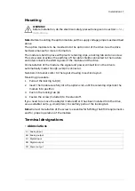
Страница 17: ...power connection to the drive is automatically made through a 20 pin connector Numbers in brackets refer to the layout drawing in section layout Mounting procedure 1 Pull out the locking tab 8 2 Inser...

Страница 18: ...1 Description Direction Name Pin Channel A DI A 1 Channel B DI B 2 Channel Z DI Z 3 Common COM_C 4 Supply voltage 5 5 V or 24 V PO VCC_ENC_1 5 Channel A DI A 6 Channel B DI B 7 Channel Z DI Z 8 Common...

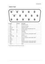
Страница 19: ...r temperature sensor COM_B 4 Excitation signal AO EXCITATION 5 Sine signal AI SIN 6 Cosine signal AI COS 7 Chassis reserved for a twisted pair s shield1 GND 8 Common COM_B 9 Excitation signal AO EXCIT...

Страница 20: ...l Z DO EM_Z 3 Common COM_B 4 Not connected NC 5 Channel A DO EM_A 6 Channel B DO EM_B 7 Channel Z DO EM_Z 8 Common COM_B 9 Shield Shield Digital inputs for position latching X54 Description Direction...

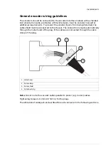
Страница 21: ...ble shield must be connected to the chassis The connection is made automatically through the metal hood of the plug if the cables are connected through the cable clamp of the plug 4 3 1 2 Metal hood 1...

Страница 22: ...er cable Z VCC_ENC_1 COM_C VCC 0V 0 2 2 1 1 0 VCC 0V VCC_ENC_1 COM_C Z B A B A OPTIONAL 1 6 2 1 5 7 3 6 9 8 5 9 4 Notes Connecting plug pin number 9 pins Signals name Cable pair number 1 A 1 6 A 2 B 2...

Страница 23: ...NSOR 0V 0V 0V 0V GND GND GND GND SIN COS COS EXCITATION EXCITATION PTC KTY 84 PTC KTY_0V 11 1 1 7 2 5 Notes Connecting plug pin number 9 pins Signals name Cable pair number 6 SIN 1 1 SIN 7 COS 2 2 COS...

Страница 24: ...or to the encoder module only if there is double or reinforced insulation between the live parts of the motor and the sensor The module does not provide a safe isolation from the drive Refer to the dr...

Страница 25: ...cable pairs EM_A EM_B EM_B EM_Z EM_Z COM_B COM_B EM_A COM B 5 1 1 6 1 7 2 5 1 4 3 6 9 9 8 2 0 0V 0V 0 2 Notes Connecting socket pin number 9 pins Signals name Cable pair number 1 EM_A 1 6 EM_A 2 EM_B...

Страница 26: ...or position latching X54 3 DI1 DI2 VCC COM_C DI2 DI1 4 5 6 1 1 1 2 2 VCC 0V 2 Notes Connecting header pin number 6 pins Signals name Cable pair number 1 24V_C 1 2 COM_C 3 DI_1 2 4 DI_1 5 DI_2 3 6 DI_2...

Страница 27: ...most encoders have channel 1 leading channel 2 as illustrated below Determine the leading channel by referring to the encoder documentation or by measuring with an oscilloscope A or A or 1 A or A or 1...

Страница 28: ...equency Amplitude Excitation Signal 100 mArms 1 20 kHz 4 12 Vrms The following figure shows the SIN and COS outputs and the excitation signal 90 180 270 Zero position Zero position Carrier in phase wi...

Страница 29: ...ctions on starting up the Encoder Interface module Programming The FEN 21 is programmed through drive parameters These parameters must be checked and adjusted according to the encoder data sheet For f...

Страница 30: ...30...

Страница 31: ...the LED signals is presented below Description Colour OK Green STATUS LED Not initialized or communication fault to control unit Orange Not in use Red Encoder s OK Green ENC ST LED TTL encoder X51 fau...

Страница 32: ...32...

Страница 33: ...Technical data Contents of this chapter This chapter contains the technical data of the Resolver Interface module 7 Technical data 33...

Страница 34: ...umption of encoders latches and cabling 5W Max power consumption IP20 Degree of protection The applicable ambient conditions specified for the drive in its Hardware Manual are in effect Ambient condit...

Страница 35: ...Resolver interface AC 4 12 Vrms 100 mA max Output voltage 2 7 Vrms Sine and cosine differential inputs KTY84 or PTC thermistor input Thermistor Position resolution 24 bit Performance Speed resolution...

Страница 36: ...36...

Страница 37: ...by navigating to www abb com searchchannels Product training For information on ABB product training navigate to new abb com service training Providing feedback on ABB manuals Your comments on our man...

Страница 38: ...www abb com drives 3AFE68784859D Copyright 2023 ABB All rights reserved Specifications subject to change without notice 3AFE68784859 Rev D EN 2023 07 14...

Отзывы: