ABB FEN-11 Скачать руководство пользователя страница 1

English . . . . . . . . . . . . . . . . . . . . . 2
Deutsch . . . . . . . . . . . . . . . . . . . . 7
Italiano . . . . . . . . . . . . . . . . . . . . 12

3AFE68784964 Rev D

Effective: 28.04.2023

 2023 ABB Oy. All rights reserved.

ABB DRIVES

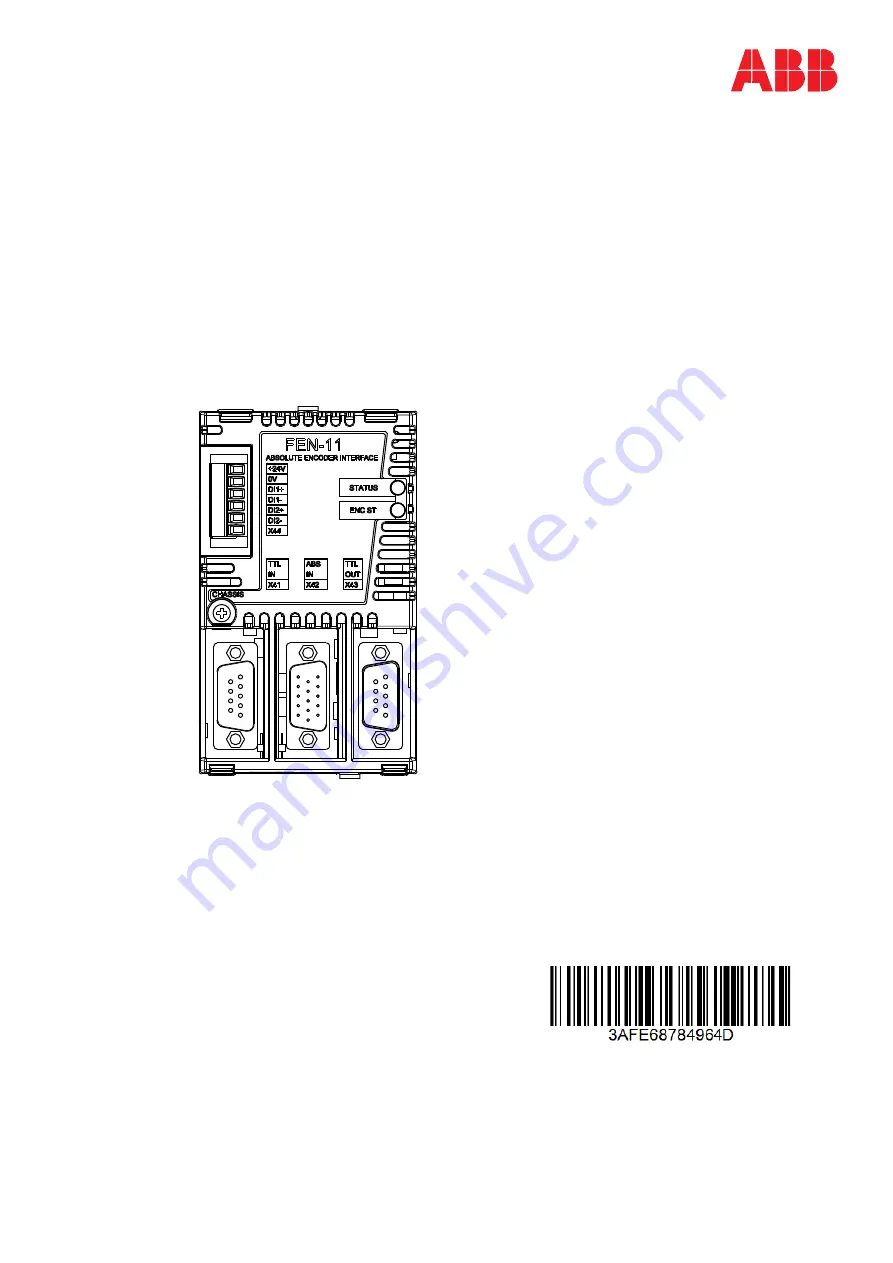
FEN-11 Absolute Encoder Interface

Quick guide

Содержание FEN-11

Страница 1: ...English 2 Deutsch 7 Italiano 12 3AFE68784964 Rev D Effective 28 04 2023 2023 ABB Oy All rights reserved ABB DRIVES FEN 11 Absolute Encoder Interface Quick guide...

Страница 2: ...apacitors 5 minutes to discharge before working on the frequency converter the motor or the motor cable Lock out and tag out Check with a voltage tester that the drive is in fact discharged before beg...

Страница 3: ...external power supply is used the appropriate jumper must be removed Note If another FEN interface s TTL emulation output is connected to TTL input the appropriate jumper must be removed Mounting WARN...

Страница 4: ...between the live parts of the motor and the sensor The module does not provide a safe isolation from the drive Refer to the drive manuals for more information The encoders should be connected to the F...

Страница 5: ...re Manual Layout and connections 106 mm 4 17 in 1 Diagnostic LEDs 2 Fixing screw 3 TTL encoder input X41 4 Absolute encoder input with PTC KTY support X42 5 TTL encoder output X43 6 2 digital latch in...

Страница 6: ...9 8 3 7 2 6 1 FEN 11 X44 DI1 DI1 DI2 DI2 VCC COM_C 0V VCC 2 2 1 1 2 1 6 5 4 3 FEN 11 X42 COS_CM COS_CM DATA Z DATA Z PTC Pt1000 KTY 84 PTC Pt1000 KTY_0V 0V SENSOR 0 0 4 4 5 1 15 11 4 3 15 14 13 9 6 SI...

Страница 7: ...ondensatoren entladen k nnen bevor Sie mit Arbeiten am Frequen zumrichter dem Motor oder dem Motorkabel beginnen Verriegeln und markieren Pr fen Sie vor Beginn der Arbeiten mit einem Spannungs messger...

Страница 8: ...xternen Spannungsversorgung mussder entsprechende Jumper entfernt werden Hinweis Wenn der TTL Emulationsausgang eines anderen FEN Schnittstellenmodulsan den TTL Eingang angeschlossen wird muss der ent...

Страница 9: ...otors und dem Sensor eine doppelte oder verst rkte Isolierung vorhanden ist Das Modul erm glicht keine sichere Trennung vom Frequenzumrichter Weitere Informationen finden Sie in den Frequenzumrichter...

Страница 10: ...rs Aufbau und Anschl sse 106 mm 4 17 in 1 Diagnose LEDs 2 Befestigungsschraube 3 TTL Inkrementalgebereingang X41 4 Absolutwertgebereingang mit PTC KTY Unterst tzung X42 5 TTL Inkrementalgeberausgang X...

Страница 11: ...4 9 8 3 7 2 6 1 FEN 11 X44 DI1 DI1 DI2 DI2 VCC COM_C 0V VCC 2 2 1 1 2 1 6 5 4 3 FEN 11 X42 COS_CM COS_CM DATA Z DATA Z PTC Pt1000 KTY 84 PTC Pt1000 KTY_0V 0V SENSOR 0 0 4 4 5 1 15 11 4 3 15 14 13 9 6...

Страница 12: ...otore attendere sempre cinque minuti per consentire la scarica dei condensatori del circuito intermedio Bloccare i componenti e contrassegnarli adeguatamente Verificare con un misura tore di tensione...

Страница 13: ...alimentazione esterna rimuovere il ponticello adeguato Nota se all ingresso TTL collegata un altra uscita di emulazione TTLdell interfaccia FEN rimuovere il ponticello adeguato Montaggio AVVERTENZA Pr...

Страница 14: ...sotto tensione del motore Il modulo non fornisce un isolamento sicuro dal convertitore di frequenza Consul tare i manuali del convertitore di frequenza per ulteriori informazioni Gli encoder dovrebbe...

Страница 15: ...ware del convertitore di frequenza Configurazione e collegamenti 106 mm 4 17 in 1 LED diagnostici 2 Vite di fissaggio 3 Ingresso encoder TTL X41 4 Ingresso encoder assoluto con supporto PTC KTY X42 5...

Страница 16: ...9 8 3 7 2 6 1 FEN 11 X44 DI1 DI1 DI2 DI2 VCC COM_C 0V VCC 2 2 1 1 2 1 6 5 4 3 FEN 11 X42 COS_CM COS_CM DATA Z DATA Z PTC Pt1000 KTY 84 PTC Pt1000 KTY_0V 0V SENSORE 0 0 4 4 5 1 15 11 4 3 15 14 13 9 6...

Отзывы: