- -
+
RA
R
+
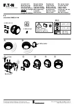
110 mm
72 mm
9 mm
110 mm
54 mm
Detector
De base
Application
Two types of detector bases are available for connection and
installation of the detectors. If the detectors are connected to
a fire control panel, the base FC600/BR is used. When con-
necting using 4-wire technology, for example, to an Intrusion
Alarm Panel or a KNX Zone Terminal, the relay base FC600/
BREL should be used (see separate data sheet).
The resistor that triggers the alarm is soldered into the detec-
tor base ex-works. The end of line resistor is connected to the
last base of a detector group in accordance with the connec-
tion schematic.
An LED on the detector head indicates the state of the detec-
tor. Optionally, a remote indicator (PA58-3) for remote signal-
ling of an alarm can be connected to the detector base (see
circuit diagram).
Electrical connection - circuit example with 3 detectors
Unlatching the detector I Dimensional drawing
Automatic Fire Detector in Threshold Alarm Technology
Should there be a requirement to hinder easy removal of the
detector from the base, a small plastic peg on the side of the
detector base can be broken off by inserting a solid object
through the aperture on the detector base. Only after insertion
at the same point, for example, of a screwdriver, is it possible
to unlatch the detector and turn it out of the base
(see “Unlatching the detector” illustration below).
Engineering
The number of detectors and the installation locations result
from the engineering specifications for fire detectors
VDE 0833 – part 2 and the engineering guidelines compliant
to VdS 2095, should there be any insurance related
requirements.
RA
-
Knock out
- -
+
RA
R
+
BM
Detector
circuit
- -
+
RA
R
+
- -
+
RA
R
+
+
Parallel display
(can be used on each
detector if required)
Detector circuit termination
resistor in the last detector – 5.6 k
Ω
Address module
(can be used on each
detector if required)
If a series resistor is not integrated
before the LED in the detector parallel display,
a 1 k
Ω
resistor must be used at this point!
+
-
Note:
Address module and parallel display are only displayed for the purpose of example and are not absolutely necessary!
NG58/1