


12/17
3.2
Installation
The connection diagram printed on the housing needs to be considered connecting the me-
ter to the mains power.
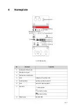
4. Connection diagram
Nr.
Terminal
Terminal
Nr.
Terminal-
Ø[mm]
Terminal screw
Torque M [Nm]
1
Current In L1
1
6,3*5,6
(L*W)
M4
Pozidrive PZ1
Philips PH1
1,2 Nm< M < 1,5Nm
2
Current Out L1
3
3
Voltage
4
Data Interface
1
RS485 Interface B
22
5,0 x 3,2
(L*W)
M3 Pozidrive PZ1
Philips PH1
0,5Nm < M < 0,7Nm
2
RS485 Interface A
23
Warning
The requirements of the net provider need to be full filled.
Selective hedges must be used according to requirements of the net providers.