

Power supply (24V DC) for EP010 comes from the FBP.
Connected Modbus device, however, must be independently powered.
Protective Earth (PE) must be connected to earth.
Suitable ABB field bus plug types
DeviceNet
yes
PROFIBUS DP
yes
Connected device communication parameters have to be:
Table 2. Device communication parameters
2
Replacement of a defective EP010
A defective EP010 can be replaced without any problems. After disconnecting
Modbus cables and the FieldBusPlug, the EP010 can be dismounted and replaced.
3
Mechanical Data
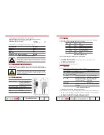
Figure 2. Dimensions for mounting
Slave Address
247 (0xF7)
Baudrate
19200
Parity
Even
Stop bits
1
Addressing Type (where applicable)
Standard
Mounting on DIN rail
according to DIN EN 50022-35
The DIN rail is positioned
aligned between the top edge
and the lower edge of the unit.
Width x Height x Depth
36 x 90 x 62 mm
Conductor cross section max. 2.5 mm2
Weight
0.102 kg
Dimensions for mounting refer to the following figure
1SDH000509R0001
L3116
E P 0 1 0
ABB SACE
N° Pag.
2/4
4
Start-up
At power up or after a reset, beginning with all the LEDs switched OFF, a diagnostic
process starts and the following sequence is performed:
Table 3. Start-up LEDs sequence
Then all LEDs stay ON for about 500 ms. After this time:
1. all the LEDs are switched OFF
2. the WD LED flashes a number of times depending on the device that can be
connected on the Modbus Port
3. the EP010 enters in Run state.
The total start-up time is less than 3 [s].
5
Run State
The table reports the normal behaviour of LEDs in this state.
(1) If the FBP is disconnected, the EP010 is powered off.
After a failure has been detected and signalled, the FAULT LED continues flashing until:
1. the FBP is communicating with the EP010 (and then the EP010 is communicating with
the device using the Modbus port) and the fault is removed OR
2. the EP010 is power off (i.e. the FBP is disconnected) or reset.
Step
LED
Colour
ON
1
WD
Red
Power-on
2
RX
Green
RAM and Code Tests passed
3
FBP
Green
External clock ready
4
FAULT
Yellow
Diagnostic completed
5
TX
Green
Ready
LED
Colour ON
OFF
GENERIC FLASHING
PWR Green FBP connected FBP disconnected (1)
WD
Red
Watchdog expired
TX
Green
FBP doesn’t communicate
FBP communicates AND
communicate with EP010
Modbus query to PU sending
RX
Green
FBP doesn’t communicate
FBP communicates AND
with EP010 OR no response Modbus response from
from PU (if TX flashes)
PU receiving
FAULT Yellow
See section 6
FBP
Green
FBP doesn’t communicate
FBP communicates with EP010
with EP010
Table 4. Normal LEDs behaviour
1SDH000509R0001
L3116
E P 0 1 0
ABB SACE
N° Pag.
3/4
Installation and maintenance have to be performed according to the technical
rules, codes and relevant standards e.g. EN 60204 part 1 by skilled
electricians only.
Remember that the address associated to the device via the EP010 is stored
into the FBP. Therefore, after installation, the new EP010 takes on the same
address as the replaced one.


