

2.5 Technical data
Fuse
For detailed in
formation on cables, connectors, circuit breakers, braking
resistors, filters, Ferrite ring an
d fans,
please refer to chapter
3.6
Accessories
in
the E530-EC Servo system user manual (3AXD50001018672 [EN]).
2.6 Drive and motor configuration table
2.7 Cable specifications
Terminal data for power cables
Terminal data for the control cables
Terminal data for motor and encoder
For the technical data and speed torque curve of the motor, please refer to
chapter
3.6 Accessories
in the E530-EC Servo system user manual
(3AXD50001018672 [EN]).
3. Installing the Drive
3.1 Environmental standards
1)
For 2kW drive with 1-phase 220V input, the rated output of motor torque is
derated to 80%.
3.2 Installing oriental
E530 EtherCAT variant servo drive only supports vertical mounting. Improper
installation orientation may cause overheat and damage to the drive.
3.3 Installing clearance
When installing the drive vertically, the thermal dissipation minimum space
requirement for is shown as below. Different frame sizes have different free
space requirement. Frame sizes F2 and F3 should have a space of more than
10mm reserved on both sides of the drive, and a space of more than 100mm
above and below the drive.
F2 and F3 support compact installation, but the rated load should be reduced to
80% in this case
.
For frame size F4, a space of more than 40 mm should be reserved on the left
side (connection requirements), and a space of more than 100 mm above and
below the drive
.
3.4 Drive weight
3.5 Drill holes and outline dimensions
F2, F3
Note:
For F2, there is no a hole in the bottom left corner of the Front view.
F4
4. Basic Inspection
5. Main circuit wiring
Before wiring the servo drive, perform an insulation check on the power cable
according to safety regulations.
The main circuit of E530 EtherCAT variant servo drive is shown in the figure
below, which consists of three parts: AC power input, motor power output and
external brake resistor.
AC power input:
•
F2/F3:1-phase 220V input,only connect L1/L2,
•
F4:1-phase or 3-phase 220V input,1-phase input connect any two of L1/
L2/L3,2kW 1-phase input derating to 80%.
For detailed information on the definition of AC input terminals, definition of
drive port voltage level, wire diameter specifications of power cables, and
terminal selection of power cables, see chapter
5.3 Main Circuit Wiring
in the
E530-EC Servo system user manual (3AXD50001018672 [EN]).
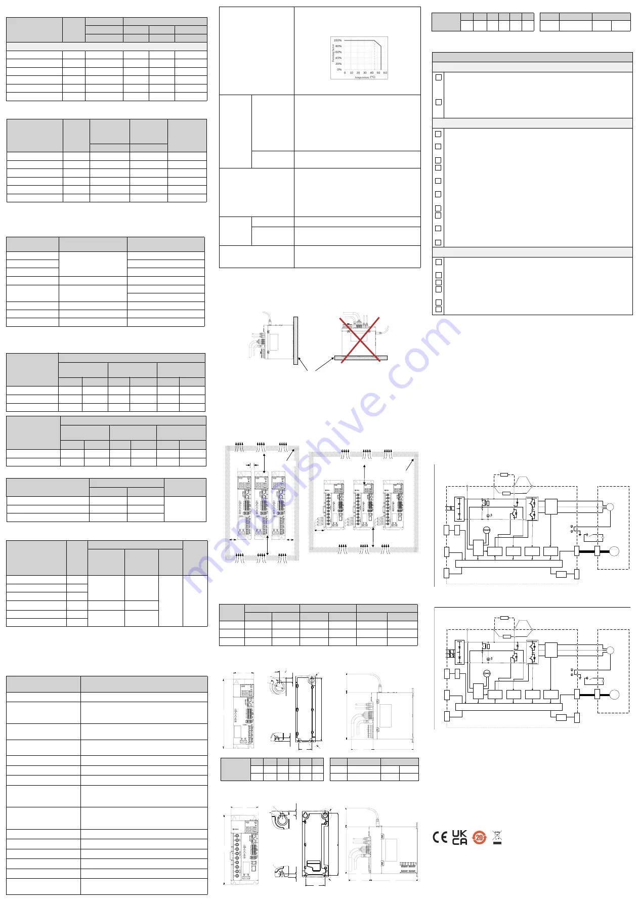
6. Control diagrams
200W~1kW: 1-phase 220V input
1. * For 200W/400W, without integrated braking resistor and without fan.
2. For 750W/1kW, with integrated braking resistor and with fan.
1.5kW/2kW:1-phase or 3-phase 220V input, with integrated
braking resistor and with fan
7. Commissioning
For commissioning procedure,
see the chapter
Tuning
,
Control panel,
and
section
2.7 Quick installation and commissioning flowchart
in
E530-EC Servo
system user manual (3AXD50001018672 [EN]).
8.
Fault tracing
For detailed information on servo drive faults, alarms, see the chapter
Fault
tracking
in
E530-EC Servo system user manual (3AXD50001018672 [EN]).
9.
Markings
A CE mark is attached to the drive to verify that the unit follows the provisions
of the European Low Voltage, EMC, RoHS and WEEE Directives. Applicable
certification marks are displayed on the type label of the drive.
For more detailed information, see the section
3.8 CE marking
in the E530-EC
Servo system user manual (3AXD50001018672 [EN]).
10
Disclaimers
For more detailed information of disclaimers, see the section
3.12 Disclaimers
in
the E530-EC Servo system user manual (3AXD50001018672 [EN]).
Type
Frame
size
Input rating
Output rating
I
1N
I
2N
I
2max
P
N
A
A
A
kW
200W~1kW, 1-phase, U
N
=200...240V; 1.5kW/2kW, 1 or 3-phase, U
N
=200...240V
E530-EC0S-0KW2-1
F2
2.5
1.50
4.50
0.20
E530-EC0S-0KW4-1
F2
4.7
2.90
8.70
0.40
E530-EC0S-0KW8-1
F3
8.5
5.00
15.00
0.75
E530-EC0S-1KW0-1
F3
10.0
5.35
16.05
1.00
E530-EC0S-1KW5-2
F4
6.4
7.60
22.80
1.50
E530-EC0S-2KW0-2
F4
8.0
10.10
30.30
2.00
Drive type
Frame
size
Input current
RMS
Minimum
short circuit
current
Bussmann
type
A
kA
E530-EC0S-0KW2-1
F2
2.5
5
C10G10
E530-EC0S-0KW4-1
F2
4.7
5
C10G10
E530-EC0S-0KW8-1
F3
8.5
5
C10G20
E530-EC0S-1KW0-1
F3
10.0
5
C10G20
E530-EC0S-1KW5-2
F4
6.4
5
C10G25
E530-EC0S-2KW0-2
F4
8.0
5
C10G25
Rated power
E530 EtherCAT variant
servo drive type
DSM motor type
0.05 kW
E530-EC0S-0KW2-1
DSM04L-0KWA-302-XXXX0
0.1 kW
DSM04L-0KW1-302-XXXX0
0.2 kW
DSM06L-0KW2-302-XXXX0
0.4 kW
E530-EC0S-0KW4-1
DSM06L-0KW4-302-XXXX0
0.75 kW
E530-EC0S-0KW8-1
DSM08L-0KW8-302-XXXX0
DSM08M-0KW8-302-XXXX0
1 kW
E530-EC0S-1KW0-1
DSM13M-1KW0-202-XXXX0
1.5 kW
E530-EC0S-1KW5-2
DSM13M-1KW5-202-XXXX0
2.0 kW
E530-EC0S-2KW0-2
DSM13M-2KW0-202-XXXX0
Rated power
L1, L2, L3,
P, R, C, N
terminals
Min
(solid/stranded)
Max
(solid/stranded)
Tightening
torque
mm
2
AWG
mm
2
AWG
N·m
ldf·in
0.2/0.4 kW
0.75
18
2.5
13
-
-
0.75/1.0 kW
1.50
1
6
2.5
13
-
-
1.5/2.0 kW
2.5
13
6.0
10
1.4±0.2 12.39±1.8
Rated power
U, V, W terminals
Min
(solid/stranded)
Max
(solid/stranded)
Tightening torque
mm
2
AWG
mm
2
AWG
N·m
ldf·in
0.2/0.4/0.75/1.0 kW
0.75
18
2.5
13
-
-
1.5/2.0 kW
2.0
14
6.0
10
1.4±0.2 12.39±1.8
Type
16 core I/O signal cable size
Description
mm
2
AWG
Bare wire
0.2~1.5
24~16
Stripping or
terminal length
10mm
Tubular bare terminal
0.25~1.5
23~16
Tubular pre-insulated terminals
0.25~0.75
23~19
Motor type
Flange
size
(mm)
Cable cross-section of cores
Length
Motor power
cable
(With brake)
Motor
power cable
(Without
brake)
Encoder
cable
DSM-04L-0KWA/1-302
40
0.75+0.3 mm
2
0.75 mm
2
24AWG/
26AWG
3/5/10/
15
/20/30
m
DSM-06L-0KW2/4-302
60
DSM-08L/M-0KW8-302
80
DSM-13M-1KW0-202
130
1.3+0.5 mm
2
1.3 mm
2
DSM-13M-1KW5-202
130
2+0.5 mm
2
2 mm
2
DSM-13M-2KW0-202
130
Parameter
Description
Drive type
E530-EC0S-xKWx-x
Main power supply
0.2~1.0kW:1-phase 200~240V,-15%~+10%;
1.5kW~2kW
1)
:1-phase/3-phase 200~240V,
-15%~+10%; 50/60Hz,- 5%~+5%
Frame size
F2: 0.2kW/0.4kW; F3: 0.75kW/1.0kW; F4: 1.5 kW/
2.0kW
Operating environment
Indoor (no direct sunlight), no corrosive gas,
flammable gas, oil gas or dust.
Storage temperature (°C)
-20°C ~ +65°C
Transport temperature (°C) -20°C ~ +65°C
Relative humidity (RH)
0 ~ 90% (on-condensing)
Installation altitude (m)
<1000 m (without derating); 1000 m - 2000 m
(with derating), the derating is 1% for every
100m increasing.
Atmospheric pressure (kPa)
Atmospheric pressure range 86 kPa ~ 106 kPa.
Please contact the manufacturer if it exceeds the
range.
Degree of protection
IP20
Protective class
PC1
Degree of Pollution
PD2
Power grid type
TT/TN
Overload capacity
300%
Lifetime
40,000 hours (Average 20 hours / day, 80% load
at 30°C).
Operating temperature (°C)
Operation temperature:
0°C~55°C; (0°C~45°C, no derating; 45°C~55°C
derating as 80%, the derating is 2% for every 1°C
increasing), see the figure below:
Maximum surrounding air temperature is 55°C
(open type).
Mechanica
l Vibration
Operation
The vibration test in operation: test meets
standard IEC 61800-5-1, and the test method
according to sine vibration in IEC 60068-2-6.
10 Hz ~ 58 Hz: 0.075 mm deflection;
58 Hz ~ 200 Hz: 1 g acceleration;
Quantity of cycles: 10 per axis XYZ;
Sweep speed: 1 octave/min.
Storage/
Transport
ISTA1A
Mechanical shock
The shock test in operation: test meets standard
IEC 61131-2, and the test method according to
the half sine wave shock in IEC 60068-2-27.
15 g peak acceleration; 11 ms duration;
Quantity of cycles: 3 times per axis XYZ in both
positive and negative directions, totally 18 times.
Free fall
Operation
Not allowed.
Storage/
Transport
76 cm
Degree of over Voltage
According to IEC/EN 60664-1 standard:
1 - phase AC 220V: category II (IEC/EN 60664-1);
3 - phase AC 220V: category III (IEC/EN 60664-1)
Frame
size
Net weight
Gross weight
Package net weight
kg
lb
kg
lb
kg
lb
F2
0.77
1.71
1.06
2.34
0.28
0.63
F3
1.08
2.38
1.42
3.13
0.34
0.74
F4
1.60
3.54
2.01
4.43
0.40
0.89
Cabinet wall
Vertical installation
Not support horizontal installation
cabinet wall
10 mm
10 mm
10 mm
Air inlet
Air outlet
Air inlet Air inlet
Air inlet Air inlet Air inlet
Air outlet
Air outlet
Air outlet
Air outlet Air outlet
F2, F3
F4
cabinet wall
≥
40 mm
≥
100 m
m
≥
100 m
m
≥
100
m
m
≥
100 m
m
Front view
Back view
Side view
W
H1
L1
L2
D2
A
B
∅
5.5
5.5
∅
5.5
∅
12
10
6.5
A
H3
D1
B
H2
Main
dimensions
/mm
W
H1
H2 H3
D1
D2
Screw Screw torque Drill hole/mm
40
202 175 70 150 80
2/ pcs M5 , 3.0/ N.m L1: 190 L2: 20
60
202 175 70 150 80
3/ pcs M5 , 3.0/ N.m L1: 190 L2: 40
Front view
Back view
Side view
W
H1
L1
L2
A
A
B
∅
5.5
5.5
∅
5.5
∅
12
B
6.5
H3
D1
H2
D2
Items
General inspection
Regularly check the servo drive's screws, motor shafts, terminals, and
connections to the mechanical system for looseness and eccentricity, and
tighten the screws if necessary, as they may loosen due to vibration and
temperature changes.
Make sure that oil, water, metal dust or any foreign objects do not fall into
the servo drive, motor, control panel or fan as these can cause damage to
the equipment.
Inspection before operation
To avoid electric shock, be sure to connect the ground terminal of the
servo drive to the ground protection terminal of the control cabinet.
Before making any connections, disconnect the power and wait 5 minutes
for the capacitors to discharge or use a suitable discharge device.
Make sure all terminals are properly insulated.
Make sure all systems are wired correctly, otherwise equipment damage
and malfunction may result.
Visually inspect to make sure there are no unused screws, metal bars, or
any conductive or flammable material inside the drive.
Never put flammable objects on the servo drive or close to the external
regenerative braking resistor.
Make sure the emergency stop switch is off.
If an electromagnetic brake is used, please make sure that its circuit for
cutting off the power is normal and effective.
If necessary, use appropriate electronic filters to eliminate
electromagnetic interference.
Make sure the external voltage to the drive is correct.
Inspection during operation
When the motor is running, pay close attention to the encoder cable
connections for damage, wear, or overextending.
Check for abnormal vibrations and sounds during operation.
Make sure all parameters are set correctly.
When resetting the parameters, make sure that the drive is in the servo
stop state. Otherwise, malfunction may result.
Ensure correct operation when using relays.
Check the power indicator and LED display for any abnormality.
L2
Control Unit
Control
circuit
power
supply
Gate drive
Voltage
detection
Overcurrent
protection
Current
detection
CN
1
IO
Cooling Fan
Ύ
CN
2
CN
4
PHY
Encoder
ƚŚĞƌŶĞƚƉŽƌƚ
Servo drive
Diode stack
L1
L1
Regenerative option
P
Regenerative
TR
Charge
light
Relay
Short for internal
brake resistor
Current
detector
U
V
W
U
V
W
U
V
W
U
V
W
Servo motor
M
E
RA
B1
B2
B
Electromagnetic
brake
24V DC
N
BO
P
Control panel
CN3
PHY
EtherCAT
R
C
/ŶƚĞŐƌĂƚĞĚďƌĂŬĞ
ƌĞƐŝƐƚŽƌΎ
L2
Control Unit
Control
circuit
power
supply
Gate drive
Voltage
detection
Overcurrent
protection
Current
detection
CN
1
IO
Cooling Fan
CN
2
CN
4
PHY
Encoder
ƚŚĞƌŶĞƚƉŽƌƚ
Servo drive
Diode stack
L1
Regenerative option
P
Regenerative
TR
Charge light
Relay
Short for internal
brake resistor
Current
detector
U
V
W
U
V
W
U
V
W
U
V
W
Servo motor
M
E
RA
B1
B2
B
Electromagnetic
brake
24V DC
N
L3
BO
P
Control panel
CN3
PHY
EtherCAT
R
C
/ŶƚĞŐƌĂƚĞĚďƌĂŬĞ
ƌĞƐŝƐƚŽƌ
Main
dimensions
/mm
W
H1
H2 H3 D1
D2
Screw Screw torque Drill hole/mm
80
202 175 70 175
80
4 / pcs M5 , 3.0/ N.m L1: 190 L2: 60