background image


Section-2 


04-3006_S2_OPM_ABB_DPA_UPSCALE_RI_10-80kW_EN_150316.doc 

Page  13/14   ABB 


Modifications reserved


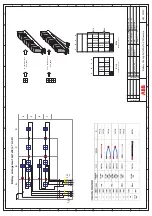
DPA UPScale RI 22 


DPA UPScale RI 22 

Module 


Module 

Module 

Module 


10

x7

Ah


10

x7

Ah


10

x7

Ah


10

x7

Ah


10

x7

Ah


10

x7

Ah


2x5

x

7Ah


10

x7

Ah


10

x7

Ah


10

x7

Ah


10

x7

Ah


10

x7

Ah


10

x7

Ah


(1x50)x7Ah 

(2x40)x7Ah 


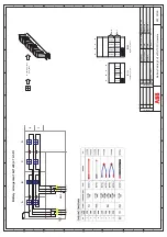
DPA UPScale RI 24  


DPA UPScale RI 24 

Module 


Module 

Module 

Module 


1

0

x

7

A

h


1

0

x

7

A

h


1

0

x

7

A

h


1

0

x

7

A

h


1

0

x

7

A

h


10x

7

A

h


2

x

5

x

7

A

h


1

0

x

7

A

h


1

0

x

7

A

h


1

0

x

7

A

h


1

0

x

7

A

h


1

0

x

7

A

h


1

0

x

7

A

h


10

x

7

A

h


1

0

x

7

A

h


1

0

x

7

A

h


1

0

x

7

A

h


1

0

x

7

A

h


1

0

x

7

A

h


2x5

x

7

A

h


1

0

x

7

A

h


1

0

x

7

A

h


1

0

x

7

A

h


1

0

x

7

A

h


1

0

x

7

A

h


1

0

x

7

A

h


  2x(1x50)x7Ah 


2x(2x40)x7Ah 


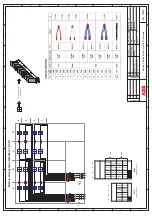
Other combination possible: refer to Section 10 

Содержание DPA Upscale M 10

Страница 1: ...DPA UPSCALETM RI 10 80 kW User Manual 04 3006_S0_OPM_ABB_DPA_UPSCALE_RI_10 80kW_EN_150316 doc Edition 18 06 2012 Copyright 2015 ABB All rights reserved ...

Страница 2: ...06_S0_OPM_ABB_DPA_UPSCALE_RI_10 80kW_EN_150316 doc Page 2 8 ABB Modifications reserved Contact us www abb com ups ups sales ch abb com Copyright ABB All rights reserved Specification subjects to change without notice ...

Страница 3: ...Y CONFORMITY AND CE MARKING 1 2 6 INQUERIES 1 3 SYSTEM DESCRIPTION 1 3 1 GENERAL SYSTEM DESCRIPTION 1 3 2 DPA UPSCALE STTM BASIC SYSTEM CONFIGURATION 1 3 3 QUALITY STANDARDS AND UPS CLASSIFICATION CODE 1 3 4 SINGLE PARALLEL MODULES OPERATION 1 4 DELIVERY TRANSPORT STORAGE 1 4 1 INTRODUCTION 1 4 2 RECEIPT OF THE UPS AND VISUAL INSPECTION 1 4 3 UNPACKING 1 4 4 NAMEPLATE AND IDENTIFICATION 1 4 5 BATT...

Страница 4: ...ACING 3 1 1 CUSTOMER INTERFACE AND DRY PORTS VOLT FREE CONTACTS 3 1 2 JD1 RS232 COMPUTER INTERFACE 3 1 3 USB COMPUTER INTERFACE 4 SECTION 4 4 1 OPERATION 4 1 1 COMMISSIONING 4 1 2 CONTROL PANEL 4 1 3 DESCRIPTION OF THE LCD 4 1 4 OPERATING MODES 5 SECTION 5 5 1 OPERATION PROCEDURES 5 1 1 START UP PROCEDURE 5 1 2 SHUTDOWN PROCEDURE 5 1 3 LOAD TRANSFER FROM INVERTER OPERATION TO MAINTENANCE BYPASS 5 ...

Страница 5: ... MAINTENANCE 7 1 3 DEEP BATTERY TEST 7 1 4 BATTERY MAINTENANCE DISPOSAL AND RECYCLING 8 SECTION 8 8 1 TROUBLESHOOTING 8 1 1 ALARMS 8 1 2 MENU COMMANDS EVENT LOG MEASUREMENTS 8 1 3 FAULT IDENTIFICATION AND RECTIFICATION 9 SECTION 9 9 1 OPTIONS 9 1 1 INTRODUCTION 9 1 2 REMOTE SHUTDOWN RSD 9 1 3 GENERATOR ON FACILITIES GEN ON 9 1 4 WAVEMON SHUTDOWN AND MANAGEMENT SOFTWARE 9 1 5 SNMP CARD ADAPTER FOR ...

Страница 6: ... 7 STANDARDS 10 8 COMMUNICATION 10 8 1 POWER MANAGEMENT DISPLAY PMD 10 8 2 MIMIC DIAGRAM 10 8 3 DISPLAY 10 8 4 CUSTOMER INTERFACES TERMINALS X1 X2 10 8 5 CUSTOMER INPUTS DRY PORT S TERMINAL BLOCK X2 10 8 6 CUSTOMER OUTPUTS DRY PORTS TERMINAL BLOCKS X1 10 9 OPTIONS 10 9 1 SNMP CARD WAVEMON MANAGEMENT SOFTWARE 10 10 BATTERY AUTONOMIES 10 10 1 EXAMPLES OF INTERNAL BATTERY AUTONOMY OF DPA UPSCALE RI 1...

Страница 7: ...e manufacturer s qualified technicians or their certified service partners OPERATIONS INSIDE THE UPS MUST BE PERFORMED BY A SERVICE ENGINEER FROM THE MANUFACTURER OR FROM AN AGENT CERTIFIED BY THE MANUFACTURER This user manual contains guidelines to check delivery installing and commissioning of the UPS and is intended for people who plan the installation install commission and use or service the ...

Страница 8: ...availability unmatched flexibility and at the same time lowest cost of ownership in IT environments This Technical Specification provides detailed technical information on the mechanical electrical and environmental performance of the DPA UPScale model types that can support to give answers to tender and end user requirements The DPA UPScale family was designed to respond to the most stringent saf...

Страница 9: ...ATION 13 1 4 5 BATTERIES AND STORAGE 13 1 4 5 1 Storage of battery 14 1 4 5 2 Storage of UPS 14 1 5 SITE PLANNING AND POSITIONING 15 1 5 1 PLANNING BEFORE THE INSTALLATION 15 1 5 2 POSITIONING OF UPS AND BATTERY CABINET 15 1 5 2 1 Final Transport 15 1 5 2 2 Positioning 16 1 5 3 ASSEMBLING INSTRUCTIONS 17 1 5 3 1 Table of Weight 17 1 5 3 2 Mechanical Drawing Assembling and accessories DPA UPScale R...

Страница 10: ... 20 40 56 Weight of Frame with modules and w o batteries kg 39 up to 42 with 1 Module 59 up to 62 with 1 Module 75 up to 78 with 1 Module DPA UPScale RI unit UPScale RI 20 UPScale RI 22 UPScale RI 24 DPA UPScale RI Subrack Configuration accommodates Max 2 modules 10 or 20kW 2 modules 10 or 20kW with 80 x 7 9Ah batteries 2 modules 10 or 20kW with 160 x 7 9Ah batteries Max Subrack connection kW 40 4...

Страница 11: ...24 up to 136 with 4 Modules Module type unit UPScale M 10 UPScale M 20 Module rated power kW 10 20 Allowed nr VRLA 12V battery blocks No 202 50 302 50 Dimensions WxHxD mm 4821 x 132 x 540 3HU Weight kg 18 6 21 5 Colors Front RAL 9005 Approximate3 audible noise at 1m from front of one module only 100 50 Load dBA 553 493 573 493 Notes 1 482 mm is the width including the wings in the front 2 Dependin...

Страница 12: ...who plan the installation install commission and use or service the UPS The reader is expected to know the fundamentals of electricity wiring electrical components and electrical schematic symbols NOTE READ THE INFORMATION IN ORDER TO AVOID EQUIPMENT DAMAGES 1 2 2 SYMBOLS CONTROLS AND INDICATORS PROTECTIVE GROUNDING TERMINAL A terminal which must be connected to earth ground prior to making any ot...

Страница 13: ...re to the instructions in this manual Any deviations from the instructions could be dangerous to the user or cause accidental load loss THE MANUFACTURER DOES NOT TAKE ANY RESPONSIBILITY FOR DAMAGES CAUSED THROUGH WRONG MANIPULATIONS OF THE UPS SYSTEM WARNING IT IS PROHIBITED TO REMOVE ANY SCREWS FROM THE UPS SYSTEM OR FROM THE BATTERY CABINET THERE IS A DANGER OF ELECTRICAL SHOCK WARNING HIGH FAUL...

Страница 14: ...ve Humidity 95 non condensing The UPS cabinet uses forced air cooling to regulate internal component temperature Air inlets are in the bottom sides and front of the cabinet and outlets in the rear of the cabinet You must allow clearance in back of the cabinet for proper air circulation Refer to Section 1 1 5 2 2 POSITIONING for clearance requirements 1 2 5 DECLARATION OF SAFETY CONFORMITY AND CE M...

Страница 15: ... Unique Safe Swappable Modules The unique Safe Swappable feature of the Modules indicates the ability to insert and extract the electronic power modules from a larger assembly while it is powered hot The safe swappable design allows live powered modules to be attached to and removed from a powered set without causing disturbance to the operation of the load and without need to go to bypass 1 3 1 2...

Страница 16: ...sion 1 3 1 4 Feature DPA Technology Decentralized Parallel Architecture The UPS product features DPA paralleling technology that provides N X redundancy without introducing a single point of failure The products utilizing the DPA technology are completely autonomous be means of individual Power Units Bypasses CPU s Control Panels and separate battery configuration for each single module The DPA te...

Страница 17: ...s High reliability low operating cost and excellent electrical performance are only some of the highlights of this innovative UPS solution The criteria and methods implemented for the design and manufacture correspond to the most stringent quality standards The manufacturer is certified successfully in every areas according to the model of the International Standard ISO 9001 EN 29001 The Certifica...

Страница 18: ... RI 11 DPA UPScale RI 12 If a configuration consists of one single Module it is defined as a Single Module Configuration even being in different cabinets like UPScale RI 10 UPScale RI 11 UPScale RI 12 with a single Module B Parallel Module DPA UPScale RI 20 DPA UPScale RI 22 DPA UPScale RI 24 DPA UPScale RI 40 A Parallel Module is a Module that is operating in parallel with other equivalent Module...

Страница 19: ...USE SERIOUS INJURIES TO PERSONS OR ANYTHING IN THE SURROUNDING AREA STORAGE THE UPS SHOULD BE STORED IN THE ORIGINAL PACKING AND SHIPPING CARTON THE RECOMMENDED STORING TEMPERATURE FOR THE UPS SYSTEM AND BATTERIES IS BETWEEN 20 C AND 25 C THE UPS SYSTEM AND THE BATTERIE SETS MUST BE PROTECTED FROM HUMIDITY 95 NON CONDENSING 1 4 2 RECEIPT OF THE UPS AND VISUAL INSPECTION Upon receiving the UPS care...

Страница 20: ...pers and remove packing container by pulling it upwards 2 Remove the plastic cover from the UPS 3 Remove pallet from the UPS Retain the packaging materials for future shipment of the UPS Examine the UPS for any sign of damage Notify your carrier or supplier immediately if damage is apparent 4a Open the UPS door and make sure that all the UPS Modules are appropriately fitted in their UPS Compartmen...

Страница 21: ...8x665x735mm R2Uxxx UPScale RI 20 Subrack 448x440x565mm R2Uxxx UPScale RI 22 Subrack 448x798x735mm R2Uxxx UPScale RI 24 Subrack 448x1153x735mm R4Uxxx UPScale RI 40 Subrack 448x798x735mm 1 4 5 BATTERIES AND STORAGE The standard batteries of the UPS are sealed maintenance free batteries sometimes mounted in an external battery cabinet and will typically be connected when the UPS is commissioned The b...

Страница 22: ...g If the packing container is removed protect the batteries from dust and humidity WARNING SEALED BATTERIES MUST NEVER BE STORED IN A DISCHARGED OR PARTIALLY DISCHARGED STATE EXTREME TEMPERATURE UNDER AND OVERCHARGE AND OVERDISCHARGE WILL DESTROY BATTERIES 1 4 5 2 Storage of UPS If you plan to store the UPS prior to use keep the UPS unpacked in a dry clean and cool storage room with an ambient tem...

Страница 23: ...for service or periodic maintenance Requested air cooling flow should be granted The air conditioning system should have sufficient amount of air cooling needed to keep the max room temperature rise at desired level Dust or corrosive explosive gases must be absent The place is vibration free Only front access is necessary for service and maintenance If the UPS will be installed in bayed enclosures...

Страница 24: ... rack The hosting rack must have front and back opening for that air flow The cold or ambient temp air inlet is on the front the hot air outlet is on the back Back clearance of min 20 cm is required for hot air outlet External Battery If external battery are needed it s recommended to install external battery cabinet s next to the UPS unit The external battery can be placed on either side of the U...

Страница 25: ...rack are shown in fig 1 1 fig 1 7 The terminal for input and output connection is at the rear side of the sub rack The cable entry can be made from rear or from bottom side see fig 1 1 1 7 For mounting the sub rack into your mains rack you have to remove all the ups modules and the battery treys from the sub rack Please use only the slides and brackets from the delivered accessories kit see fig 3 ...

Страница 26: ...ns reserved 1 5 3 2 Mechanical Drawing Assembling and accessories DPA UPScale RI 10 See drawings on the next pages Mechanical fig 1 1_CP_DPAL RI10_04 0855_PMC40_TYPE_X1 pdf Assembling fig 2 1_CP_DPAL MONTAGGIO_RI10_PMC40_TYPE_X1 Accessories fig 3 1_CP_DPAL ACCESSORI_RI10 20_04 0865_TYPE_x1 x2 ...

Страница 27: ......

Страница 28: ......

Страница 29: ......

Страница 30: ...ifications reserved 1 5 3 3 Mechanical Drawing Assembling and accessories DPA UPScale RI 11 See drawings on the next pages Mechanical fig 1 3_CP_DPAL RI11_04 0410_PMC40_TYPE1 Assembling fig 2 3_CP_DPAL MONTAGGIO_RI11_PMC40_TYPE1 Accessories fig 3 2_CP_DPAL ACCESSORI_RI11_04 0849_TYPE1 ...

Страница 31: ......

Страница 32: ......

Страница 33: ......

Страница 34: ...ications reserved 1 5 3 4 Mechanical Drawing Assembling and accessories DPA UPScale RI 12 See drawings on the next pages Mechanical fig 1 4_CP_DPAL RI12_04 0411_PMC40_TYPE2 Assembling fig 2 4_CP_DPAL MONTAGGIO_RI12_PMC40_TYPE2 Accessories fig 3 3_CP_DPAL ACCESSORI_RI12 22_04 0850_TYPE2 3 ...

Страница 35: ......

Страница 36: ......

Страница 37: ......

Страница 38: ...ns reserved 1 5 3 5 Mechanical Drawing Assembling and accessories DPA UPScale RI 20 See drawings on the next pages Mechanical fig 1 2_CP_DPAL RI20_04 0856_PMC40_TYPE_X2 pdf Assembling fig 2 2_CP_DPAL MONTAGGIO_RI20_PMC40_TYPE_X2 Accessories fig 3 1_CP_DPAL ACCESSORI_RI10 20_04 0865_TYPE_x1 x2 ...

Страница 39: ......

Страница 40: ......

Страница 41: ......

Страница 42: ...ications reserved 1 5 3 6 Mechanical Drawing Assembling and accessories DPA UPScale RI 22 See drawings on the next pages Mechanical fig 1 5_CP_DPAL RI22_04 0412_PMC40_TYPE3 Assembling fig 2 5_CP_DPAL MONTAGGIO_RI22_PMC40_TYPE3 Accessories fig 3 3_CP_DPAL ACCESSORI_RI12 22_04 0850_TYPE2 3 ...

Страница 43: ......

Страница 44: ......

Страница 45: ......

Страница 46: ...ifications reserved 1 5 3 7 Mechanical Drawing Assembling and accessories DPA UPScale RI 24 See drawings on the next pages Mechanical fig 1 6_CP_DPAL RI24_04 0413_PMC40_TYPE4 Assembling fig 2 6_CP_DPAL MONTAGGIO_RI24_PMC40_TYPE4 Accessories fig 3 4_CP_DPAL ACCESSORI_RI24_04 0851_TYPE1 ...

Страница 47: ......

Страница 48: ......

Страница 49: ......

Страница 50: ...1 5 3 8 Mechanical Drawing Assembling and accessories DPA UPScale RI 40 See drawings on the next pages Mechanical fig 1 7_CP_DPAL_M20_0227A RI40 PMC40_TYPE_X4 04_1170 pdf Assembling fig 2 7_CP_M20_0229 MONT_RI40 04_a1_2 pdf Accessories fig 3 5_CP_DPAL ACESSORI_M20_0228A ACC_RI40 PMC40_TYPE_X4 04_1107 pdf ...

Страница 51: ......

Страница 52: ......

Страница 53: ......

Страница 54: ... Air cooling flow Module Range UPScale M10 or M20 RI10 10 12 RI 20 22 24 RI 40 Module Type UPScale M10 UPScale M20 1modulemin max 2modulesmin max 4modulesmin max Heat Dissipation with 100 NNL4 per Module W 550 1100 550 1100 1100 2200 2200 4400 Heat Dissipation with 100 NNL4 Load per Module BTU h 1887 3754 1887 3754 3774 7508 7548 15096 Airflow 25 30 C with NNL4 Load per Module m3 h 150 150 150 300...

Страница 55: ...A_UPSCALE_RI_10 80kW_EN_150316 doc Page 47 52 ABB Modifications reserved Air cooling flow outlet Air cooling flow with roof outlet Door with openings min 50mm disdance Door without openings min 200mm disdance Fig 4 2 Air cooling flow ...

Страница 56: ...N RISK OF EXPOSURE TO DANGEROUS VOLTAGES PHYSICAL INJURY OR DEATH MAY FOLLOW OR DAMAGE MAY OCCUR TO THE UPS OR THE LOAD EQUIPMENT IF THESE INSTRUCTIONS ARE IGNORED To ensure correct operation of the UPS and its ancillary equipment it is necessary to provide the mains cables with appropriate fuse protection See Section 2 chapter 2 1 2 The UPS unit has the following power connections Rectifier In Th...

Страница 57: ... and will provide additional protection to the UPS in the event of overloads and short circuits 1 6 1 1 Mains supply and Earth connection To ensure protection of personnel during the installation of UPS make sure that the connections are performed under the following conditions No mains voltage is present All Loads are shut down and disconnected UPS is shut down and voltage free UPS Module is fitt...

Страница 58: ... according to following tables MAINS INPUT CABLE UPS TERMINAL Rectifier BYPASS INPUT CABLE UPS TERMINAL Bypass Phase L1 1L1 Phase L1 2L1 Phase L2 1L2 Phase L2 2L2 Phase L3 1L3 Phase L3 2L3 NEUTRAL 1N NEUTRAL 2N EARTH PE For minimum recommended Input Cable Sections and Fuse Ratings see Section 2 chapter 2 1 2 Under the connection terminal of the UPS there is a cable fixing rail to ensure that the c...

Страница 59: ...there is a cable fixing rail to ensure that the cables have been fastened properly Ensure that the earthing is performed in accordance with the prescribed IEC Standards or with the local regulations 1 6 1 5 Connection of the Load To ensure protection of the personnel during the installation of the UPS make sure that the connections are performed under the following conditions No mains voltage is p...

Страница 60: ... covers are installed on the front and back of the enclosure Battery cabinet installation instructions have been completed Air conditioning equipment is installed and operating properly The area around the installed UPS system is clean and dust free It is recommended that the UPS be installed on a level floor suitable for computer or electronic equipment Adequate workspace exists around the UPS an...

Страница 61: ...l Version 4 2 1 3 4 Dual FEED INPUT Cable Sections 4 2 2 FRONT VIEW 5 2 2 1 FRONT VIEW OF DPA UPScale RI 10 AND CONNECTION TERMINALS 5 2 2 2 FRONT VIEW OF DPA UPScale RI 11 AND CONNECTION TERMINALS 6 2 2 3 FRONT VIEW OF DPA UPScale RI 12 AND CONNECTION TERMINALS 7 2 2 4 FRONT VIEW OF DPA UPScale RI 20 AND CONNECTION TERMINALS 8 2 2 5 FRONT VIEW OF DPA UPScale RI 22 AND CONNECTION TERMINALS 9 2 2 6...

Страница 62: ...PE Terminals T Connection Bar B Battery Earth PE Separate Battery N Common Battery N Input Bypass 3 N Input Rectifier 3 N PE Output load 3 N PE UPScale RI 10 16 25mm2 T 3 x 10 16mm2 T n a 4 x 10 16 mm2 T 5 x 10 16 mm2 T 5 x 10 16 mm2 T UPScale RI 11 n a n a n a UPScale RI 12 n a n a n a UPScale RI20 16 25mm2 T 2x 3 x 10 16mm2 T 3 x M5 B 4 x 16 25 mm2 T 5 x 16 25 mm2 T 5 x 16 25 mm2 T UPScale RI 22...

Страница 63: ...950 1 Max Input Current with battery charging A Cable D mm2 IEC 60950 1 I nom A Fuse E N Agl CB Cable E mm2 Only for external Batteries N Com Battery Sep Battery Upscale RI 10 20 3x40A 5x6 34 5x6 29 A 3x63A n a 3x10 Upscale RI 11 20 3x40A 5x6 34 5x6 29 A 3x63A n a n a Upscale RI 12 20 3x40A 5x6 34 5x6 29 A 3x63A n a n a Upscale RI 20 40 3x80A 5x16 68 5x16 58 A 3x100A 1 3x25 1 2x 3x10 Upscale RI 22...

Страница 64: ...ble C mm2 IEC 60950 1 Cable D mm2 IEC 60950 1 I nom Fuse E N Agl CB Cable E mm2 Only for external Batteries N Com Battery Sep Battery Upscale RI 10 20 3x40A 5x6 34 3x40A 4x6 5x6 29 A 3x63A n a 3x10 Upscale RI 11 20 3x40A 5x6 34 3x40A 4x6 5x6 29 A 3x63A n a n a Upscale RI 12 20 3x40A 5x6 34 3x40A 4x6 5x6 29 A 3x63A n a n a Upscale RI 20 40 3x80A 5x16 68 3x80A 4x16 5x16 58 A 3x100A 1 3x25 1 2x 3x10 ...

Страница 65: ...e contacts X1 Customer Inputs detail see Section 3 3 1 2 3 LED red green 4 JD1 RS232 Sub D9 female PC interface 5 USB PC Interface 6 SNMP Slot for optional SNMP card ONLY 7 Modem Slot for optional Modem Ethernet card ONLY 8 Battery terminal N for Single battery 10 16 mm2 9 Input Bypass terminal for Dual Input feed 10 16 mm2 10 Input Rectifier terminal for Single feed 10 16 mm2 11 Output Load termi...

Страница 66: ...minals Potential free contacts X1 Customer Inputs detail see Section 3 3 1 2 3 LED red green 4 JD1 RS232 Sub D9 female PC interface 5 USB PC Interface 6 SNMP Slot for optional SNMP card ONLY 7 Modem Slot for optional Modem Ethernet card ONLY 8 Input Bypass terminal for Dual Input feed 10 16 mm2 9 Input Rectifier terminal for Single feed 10 16 mm2 10 Output Load terminal 10 16 mm2 11 F4 1 Battery C...

Страница 67: ...minals Potential free contacts X1 Customer Inputs detail see Section 3 3 1 2 3 LED red green 4 JD1 RS232 Sub D9 female PC interface 5 USB PC Interface 6 SNMP Slot for optional SNMP card ONLY 7 Modem Slot for optional Modem Ethernet card ONLY 8 Input Bypass terminal for Dual Input feed 10 16 mm2 9 Input Rectifier terminal for Single feed 10 16 mm2 10 Output Load terminal 10 16 mm2 11 F4 1 Battery C...

Страница 68: ...2 3 LED red green 4 JD1 RS232 Sub D9 female PC interface 5 USB PC Interface 6 SNMP Slot for optional SNMP card ONLY 7 Modem Slot for optional Modem Ethernet card ONLY 8 Battery terminal N for Single battery 10 16 mm2 8 Battery terminal N for Common battery M5 9 Input Bypass terminal for Dual Input feed 16 25 mm2 10 Input Rectifier terminal for Single feed 16 25 mm2 11 Output Load terminal 16 25 mm...

Страница 69: ...tacts X1 Customer Inputs detail see Section 3 3 1 2 3 LED red green 4 JD1 RS232 Sub D9 female PC interface 5 USB PC Interface 6 SNMP Slot for optional SNMP card ONLY 7 Modem Slot for optional Modem Ethernet card ONLY 8 Input Bypass terminal for Dual Input feed 16 25 mm2 9 Input Rectifier terminal for Single feed 16 25 mm2 10 Output Load terminal 16 25 mm2 11 F4 1 Battery Circuit Breaker 3x63 A 800...

Страница 70: ...contacts X1 Customer Inputs detail see Section 3 3 1 2 3 LED red green 4 JD1 RS232 Sub D9 female PC interface 5 USB PC Interface 6 SNMP Slot for optional SNMP card ONLY 7 Slot for optional Modem Ethernet card ONLY 8 Input Bypass terminal for Dual Input feed 16 25 mm2 9 Input Rectifier terminal for Single feed 16 25 mm2 10 Output Load terminal 16 25 mm2 11 F4 1 Battery Circuit Breaker 3x63 A 800 VD...

Страница 71: ...C interface 5 USB PC Interface 6 SNMP Slot for optional SNMP card ONLY 7 Modem Slot for optional Modem Ethernet card ONLY 8 Battery terminal N for Single battery 10 16 mm2 8 Battery terminal N for Common battery M6 9 Input Bypass terminal for Dual Input feed 50 mm2 10 Input Rectifier terminal for Single feed 50 mm2 11 Output Load terminal 50 mm2 12 F4 1 Battery Circuit Breaker 2x63 A 800 VDC 13 F4...

Страница 72: ...ale Assembling S20_0020C Electric Diagram Battery Cabling 2 x 2x40 RI UPScale NOTE For UPS Systems DPA UPScale M 10kW it is allowed to use 20 50 only even numbers of 12V battery blocks depending the power sourced on the output For UPS Systems DPA UPScale M 20kW it is allowed to use 30 50 only even numbers of 12V battery blocks depending the power sourced on the output IMPORTANT For max battery aut...

Страница 73: ...7Ah 10x7Ah 2x5x7Ah 10x7Ah 10x7Ah 10x7Ah 10x7Ah 10x7Ah 10x7Ah 1x50 x7Ah 2x40 x7Ah DPA UPScale RI 24 DPA UPScale RI 24 Module Module Module Module 10x7Ah 10x7Ah 10x7Ah 10x7Ah 10x7Ah 10x7Ah 2x5x7Ah 10x7Ah 10x7Ah 10x7Ah 10x7Ah 10x7Ah 10x7Ah 10x7Ah 10x7Ah 10x7Ah 10x7Ah 10x7Ah 10x7Ah 2x5x7Ah 10x7Ah 10x7Ah 10x7Ah 10x7Ah 10x7Ah 10x7Ah 2x 1x50 x7Ah 2x 2x40 x7Ah Other combination possible refer to Section 1...

Страница 74: ...ent 2x 1x50 x 7Ah RI 3 4 A B C 4 Wire 10x 10 x battery blocks S20_0024 12V 7Ah 12V 7Ah D 10x 10x 10x 5x 10x F4 1 10x7Ah 10x7Ah 2x5x7Ah 10x7Ah 10x7Ah A B D C 5x 5x 2 x 5 x battery blocks S20_0025 12V 7Ah 12V 7Ah 12V 7Ah 5x 10x 10x 10x 5x 10x 5x 1 2 F4 1 10x7Ah 10x7Ah 2x5x7Ah 10x7Ah 10x7Ah F4 2 A B D C 10x7Ah 10x7Ah 2x5x7Ah 10x7Ah 10x7Ah RI 12 RI 24 F4 2 F4 1 04 0541 1x 1x50x7Ah 04 0522 2x 1x50x7Ah ...

Страница 75: ...attery Cabling 2x 1x40 x7Ah RI Upscale MT Battery arrangement 2x 1x40 x 7Ah RI 10x 10 x battery blocks S20_0024 12V 7Ah 12V 7Ah F4 1 10x7Ah 10x7Ah 10x7Ah A B D C F4 1 10x7Ah 10x7Ah 10x7Ah F4 2 A B D C RI 11 RI 22 F4 1 04 0540 1x 1x40x7Ah 04 0524 2x 1x40x7Ah 1 2 A B C 4 Wire D 10x 10x 10x 10x 10x 10x 10x 10x 10x7Ah 10x7Ah 10x7Ah 10x7Ah 10x7Ah 10x7Ah F4 2 B 24 02 15 MT F4 23x63A 1 3 5 2 4 6 F4 13x63...

Страница 76: ...arrangement 2x 2x40 x 7Ah RI F4 1 10x7Ah 10x7Ah 10x7Ah A B D C RI 12 04 0542 1x 2x40x7Ah 10x7Ah 10x7Ah 10x7Ah 10x7Ah 10x7Ah 1 2 3 4 A B C D 10x 10x 10x 10x 10x 10x 10x 10x 10x 10x 10x 10x 10x 10x 10x 10x F4 1 10x7Ah 10x7Ah 10x7Ah A B D C RI 24 04 0543 2x 2x40x7Ah 10x7Ah 10x7Ah 10x7Ah 10x7Ah 10x7Ah F4 2 10x7Ah 10x7Ah 10x7Ah 10x7Ah 10x7Ah 10x7Ah 10x7Ah 10x7Ah F4 1 F4 2 12V 7Ah 10x 10 x battery block...

Страница 77: ...connections are performed under the following conditions No mains voltage is present in the UPS All the loads are disconnected The UPS and the external battery are voltage free To verify the complete shut down of the DPA UPScale RI perform following steps 1 Make sure that the fuses feeding the UPS in the input Distribution Board are all open and no power is fed to the UPS 2 Make sure the MAINTENAN...

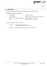
Страница 78: ...cations reserved SECTION 3 3 1 INTERFACING 2 3 1 1 Customer interface and DRY PORTs volt free contacts 3 3 1 1 1 Output Interfaces Terminal blocks X2 DRY PORTs 3 3 1 1 2 Input Interfaces Terminal blocks X1 3 3 1 2 JD1 RS232 Smart Port Computer Interface 4 3 1 3 USB Computer Interface 4 ...

Страница 79: ... to the distribution Input Interfaces X1 Phoenix terminals Output Interfaces X2 DRY PORTs volt free contacts Phoenix terminals Smart Port JD1 RS232 Sub D9 female Interface UPS system to computer USB Interface UPS system to computer On the Interface board are located two LED s 3 Green LED showing the status of the Interface Fast Blinking 2 times sec Interface is OK Red LED Board Alarm indicates a p...

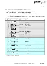
Страница 80: ...NS_OK Mains Present X2 2 NC ALARM Mains Failure X2 3 C Common X2 4 NO LOAD_ON_INV Load on Inverter X2 5 NC Message Load on Mains bypass X2 6 C Common X2 7 NO BATT_LOW Battery Low X2 8 NC ALARM Battery OK X2 9 C Common X2 10 NO LOAD_ON_MAINS Load on bypass Mains X2 11 NC Message Load on Inverter X2 12 C Common X2 13 NO COMMON_ALARM Common Alarm System X2 14 NC ALARM NO Alarm Condition X2 15 C Commo...

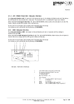
Страница 81: ...AVEMON 3 1 3 USB Computer Interface The Computer Interface USB 5 located on the distribution part and is in parallel with the intelligent RS 232 serial port JD1 When installed the USB Computer Interface trough the optional WAVEMON software allows the computer to monitor the mains voltage and the UPS system status continuously In the event of any changes the computer terminal will display a message...

Страница 82: ...ators 3 4 1 2 3 Keys 3 4 1 2 4 ON OFF Start up and Shutdown Buttons 3 4 1 3 Description of the LCD 4 4 1 3 1 Status Screens 4 4 1 3 2 Main Menu Screen 4 4 1 3 3 Event Log Screen 5 4 1 3 4 Measurements Screen 5 4 1 3 5 Commands Screen 5 4 1 3 6 UPS Data 6 4 1 3 7 Set Up User 6 4 1 3 8 Set Up Service 6 4 1 4 Operating Modes 7 4 1 4 1 Mode ON LINE INVERTER MODE 7 4 1 4 2 Mode OFF LINE ECO or BYPASS M...

Страница 83: ...ntrol Panel WARNING ONLY PERSONS WHICH HAVE BEEN TRAINED BY SERVICE TECHNICIANS OF THE MANUFACTURER OR HIS CERTIFIED SERVICE PARTNERS ARE ALLOWED TO OPERATE ON THE CONTROL PANEL WITH CLOSED DOORS ALL OTHER INTERVENTIONS ON THE UPS SYSTEM HAVE TO BE DONE ONLY BY SERVICE TECHNICIANS OF THE MANUFACTURER The user friendly control panel is composed of three parts POWER MANAGEMENT LCD DISPLAY PMD LED IN...

Страница 84: ...Mains bypass available Mains bypass not OK or not available UPS is turned off BY PASS GREEN OFF Load on bypass Bypass or Eco Mode Bypass not operating switched off INV GREEN RED OFF Load on inverter Inverter fault or load not transferable to inverter Inverter not operating switched off BATTERY GREEN RED Flashing GREEN Battery OK Battery fault or battery is discharged Battery in discharge or batter...

Страница 85: ...number The max no of module units are 2 per system EXEMPLES S stands for Single UPS The system consists of ONLY one UPS P1 stands for Parallel UPS in a Multi UPS system and 01 stands for the first Module MASTER in the Multi UPS system P2 stands for Parallel UPS in a Multi UPS system and 02 stands for the second Module SLAVE in the Multi UPS system The configuration of the single parallel UPS is ac...

Страница 86: ...00 00 11 Active Output Power of all three phases ACTIVE POWER KW 00 00 00 00 00 00 12 Reactive Output Power of all three phases REACTIVE POWER kVAr 00 00 00 00 00 00 13 Apparent Output Power of all three phases APPARENT POWER KVA 00 00 00 00 00 00 14 Output Power of all three phases OUTPUT POWER 00 00 00 00 00 00 15 Battery capacity BATT CAPACITY 00 00 4 1 3 5 Commands Screen DESCRIPTION LCD DISPL...

Страница 87: ...Y 1 Set up Language not active yet SET LANGUAGE SET DATE AND TIME ENGLISH FRANCAIS POLISH 2 Set up Date and Time SET UP DATE TIME SET UP BATT TEST DD MM YY HH MM SS 3 Set up battery test SET BATTERY TEST SET GENERATOR OP DAY OF MONTH 1 31 HOUR OF DAY 1 24 REPETITIVE Y N YES NO 4 Set up operation with Gen Set SET GENERATOR OP NO MORE SETTINGS BATT CHARGE LOCK YES NO BYPASS LOCK YES NO 4 1 3 8 Set U...

Страница 88: ...he static bypass mains supply transfer time 0 4 1 4 2 Mode OFF LINE ECO or BYPASS MODE In the OFF Line Mode the load is supplied from the mains through the static bypass Using the control panel see figure 1 1 the UPS may be easily transferred to Bypass Mode When the UPS is operating in Bypass Mode the efficiency of the system is higher In the event of a mains failure the load will automatically be...

Страница 89: ...cate as shown in table below OFF Bypass Switch Open Normal operating condition Load supplied by inverter LCD indication MANUAL BYP IS OPEN LED Indicators will indicate as shown in table below LED Indicator ON OFF LINE 1 Green Green LINE 2 Green Green BYPASS Green OFF INVERTER RED Green BATTERY Green Green Before transferring the load to Maintenance Bypass IA1 always make sure all the UPS modules a...

Страница 90: ...acement of UPS Module in Single Module Systems 7 5 2 1 1 How to Extract a UPS Module in SINGLE MODULE Systems 7 5 2 1 2 How to Fit Back a UPS Module in SINGLE MODULE Systems 8 5 2 2 Replacement of UPS Module in Redundant Multi Module System 10 5 2 2 1 How to Extract a Module in Redundant Multi Module System 10 5 2 2 2 How to insert a module in a Redundant Multi Module System 10 5 2 3 Replacement o...

Страница 91: ... the external battery cabinets are open Start up procedure of DPA UPScaleTM 1 Insert fuses for the supply of UPS System in the Input Distribution The LED indicators LINE 1 and battery on UPS Module is lit green On LCD Display LOAD OFF SUPPLY FAILURE will appear 2 UPS Module 1 Press both ON OFF Main Buttons to switch on UPS LED indicator will appear as shown below LED Indicator Colour LINE 1 Green ...

Страница 92: ...command LOAD TO BYPASS and transfer the load to mains on control panel of any one of the UPS modules Close Maintenance Bypass Switch IA1 position ON On LCD MANUAL BYP IS CLOSED will appear and the LED indicator will indicate as shown below LED Indicator Colour LINE 1 Green LINE 2 Green BYPASS Green INVERTER RED BATTERY Green 12 Connect Load to the UPS Output Insert fuses in output Distribution Boa...

Страница 93: ...ompletely shutdown The following procedures can only be executed after the load has completely been de energized NOTE IN THE CASE THAT THE PARALLEL UPS SYSTEM HAS TO BE TURNED OFF THEN BOTH ON OFF BUTTONS ON ALL UPS MODULES HAVE TO BE PUSHED IN THIS CASE THE POWER SUPPLY TO THE LOAD WILL BE INTERRUPTED 1 Verify that the loads are shutdown and that there is no need for power supply to the load 2 If...

Страница 94: ... choose command LOAD TO BYPASS and transfer the load to mains on control panel of any one of the UPS modules On LCD panel LOAD NOT PROTECTED will appear 2 Close Maintenance Bypass Switch IA1 position ON On LCD MANUAL BYP IS CLOSED will appear and the mimic panel will show LED Indicator Colour LINE 1 Green LINE 2 Green BYPASS Green INVERTER RED BATTERY Green 3 Press simultaneously the two ON OFF bu...

Страница 95: ...rs in the external battery cabinets or racks 2 On the LCD s LOAD OFF SUPPLY FAILURE will appear and the mimic panel will show LED Indicator Colour LINE 1 Green LINE 2 OFF BYPASS OFF INVERTER OFF BATTERY Flashing Green 3 Press simultaneously the two ON OFF buttons on the UPS control panel PMD on all control panels of the modules Unit will start up and after about 60 seconds the mimic panel will sho...

Страница 96: ...LY SAFEGUARD PLATFORMS AGAINST EVT FALL DOWN ARE TO BE PLANNED If your DPA UPScaleTM consists of only one single UPS Module then perform following steps to extract the module 1 Reset the Alarm on faulty Module The audible noise will stop If the Alarm condition persists the LED Indicator ALARM will remain red it means that there is a fault in the UPS Module 2 If the load is supplied by the mains in...

Страница 97: ...ht of a of UPScale M10 is 18 5 kg M20 module is 21 5kg 9 Insert new UPS Module or cover the opening UPS Module Compartment with appropriate protection cover immediately and fix with two screws WHILE THE UPS IS OPERATING IN THE MAINTENANCE BYPASS MODE THE LOAD IS NOT PROTECTED AND IN THE EVENT OF A MAINS FAILURE THE LOAD SUPPLY WILL BE INTERRUPTED AND THE LOAD WILL CRASH 5 2 1 2 How to Fit Back a U...

Страница 98: ...tart up UPS LCD panel must display LED indicator will appear as shown below LED Indicator Colour LINE 1 Green LINE 2 Green BYPASS Green INVERTER RED BATTERY Green 7 Open Maintenance Bypass IA1 by turning it to position OFF The load is now supplied by the static bypass 8 Transfer load to mains and inverter for testing using submenu COMMANDS 9 Transfer load to Inverter Mode by means of COMMAND LOAD ...

Страница 99: ...ALARM is red there is a fault in the UPS Module 2 Verify that load is supplied by inverter of the other modules running by checking the LCD indication LOAD PROTECTED Verify load measures on the operating modules 3 Turn the faulty module OFF by pressing simultaneously both ON OFF buttons On the LCD LOAD OFF SUPPLY FAILURE should appear and the LED indicator will indicate as shown below LED Indicato...

Страница 100: ... into dedicated compartment make sure not to plug the UPS Module into the rear connector Push UPS module to its final position and push strongly to assure good contact on the rear plugs Tighten the two screws on the front of module 4 Check if LED LINE1 and battery is green If yes mains voltage is OK On the LCD LOAD OFF SUPPLY FAILURE will appear and the LED indicator will indicate as shown below L...

Страница 101: ...persists the LED Indicator ALARM is red there is a fault in the UPS Module 2 Verify that the load is on Bypass and is supplied by the mains power Bypass Mode or Eco Mode on all UPS Modules in the majority of the events the LED indicators on Control Panel of the Faulty Module will show LED Indicator Colour LINE 1 Green LINE 2 Green BYPASS Green INVERTER RED BATTERY Green 3 Whereas the LED indicator...

Страница 102: ...i Module System perform following steps 1 Remove UPS Module compartment protection cover by unscrewing two screws on the front Slide two thirds of UPS Module into dedicated UPS compartment make sure not to plug the UPS Module into the rear connector Push UPS module to its final position and push strongly to assure good contact on the rear plugs NOTE We recommend 2 persons for pulling out the modul...

Страница 103: ...he static bypass of all three Modules Check LED indicators on control panels 8 Transfer load to Inverter Mode by means of COMMAND LOAD TO INVERTER on any one of control panels On LCD LOAD PROTECTED will appear and the LED indicator will indicate as shown below LED Indicator Colour LINE 1 Green LINE 2 Green BYPASS OFF INVERTER Green BATTERY Green THE LOAD IS NOW PROTECTED BY THE DPA UPScaleTM ...

Страница 104: ...Section 6 04 3006_S6_OPM_ABB_DPA_UPSCALE_RI_10 80kW_EN_150316 doc Page 1 2 ABB Modifications reserved CONTENTS SECTION 6 6 1 MULTI CABINET CONFIGURATION Not Available 2 ...

Страница 105: ...Section 6 04 3006_S6_OPM_ABB_DPA_UPSCALE_RI_10 80kW_EN_150316 doc Page 2 2 ABB Modifications reserved 6 1 MULTI CABINET CONFIGURATION NOT AVAILABLE ...

Страница 106: ...LE_RI_10 80kW_EN_150316 doc Page 1 4 ABB Modifications reserved CONTENTS SECTION 7 7 1 MAINTENANCE 2 7 1 1 User Responsibilities 2 7 1 2 Preventative Maintenance 2 7 1 3 Deep Battery Test 2 7 1 4 Battery maintenance disposal and recycling 3 ...

Страница 107: ...tial to ensure a correct functionality and reliability of the UPS system When the UPS is commissioned the commissioning field service engineer will attach a service record book to the front of the UPS and this will be used to record the full service history of the UPS During a preventative maintenance the field service engineer might carry out some or all of following checks Status and function ch...

Страница 108: ...PS display in the service setup mode 7 1 4 Battery maintenance disposal and recycling The battery maintenance shall be done by a certified Service Partner To ensure an optimum operation of the UPS system and a continuous and efficient protection of the connected load it is recommended to check the batteries every 12 months Batteries contain dangerous substances that will harm the environment if th...

Страница 109: ...Section 7 04 3006_S7_OPM_ABB_DPA_UPSCALE_RI_10 80kW_EN_150316 doc Page 4 4 ABB Modifications reserved This page left intentionally blank ...

Страница 110: ...BB_DPA_UPSCALE_RI_10 80kW_EN_150316 doc Page 1 2 ABB Modifications reserved CONTENTS SECTION 8 8 1 TROUBLESHOOTING 2 8 1 1 Alarms 2 8 1 2 Menu Commands Event Log And Measurements 2 8 1 3 Fault Identification and Rectification 2 ...

Страница 111: ...ircuit breakers etc supplying the UPS MAINS BYP FAULT Mains power supply is outside prescribed tolerance The input power to UPS is too low or missing If site power appears to be OK check the input circuit breakers etc supplying the UPS OUTPUT SHORT There is a short circuit at the output of UPS on load side Check all output connections and repair as required OVERLOAD Load exceeds the UPS rated powe...

Страница 112: ...S SECTION 9 9 1 OPTIONS 2 9 1 1 Introduction 2 9 1 2 Remote SHUT DOWN 2 9 1 3 Generator ON Facilities 3 9 1 4 Wavemon Shutdown and ManagementSoftware 3 9 1 4 1 Why is UPS Management important 3 9 1 4 2 WAVEMON Shutdown and Monitoring Software 3 9 1 5 SNMP CARD ADAPTER For Network Management Remote Monitoring 5 ...

Страница 113: ...e the remote shut down sequence The remote shutdown on terminal port X1 7 X1 8 is located at the bottom of the DPA UPSCALETM frame on communication card with terminal blocks X1 X2 See section 3 1 2 1 for details In order to allow removal maintenance or testing of any remote shut down facility without disturbing the normal operation of the UPS it is recommended that a terminal block with linking fa...

Страница 114: ...is unreliable at times ensuring that all network systems have constant power can be a difficult task The situation becomes even more complex if systems are managed across a Local Area Network LAN or Wide Area Network WAN around the world When a power failure occurs action can be taken to protect the system and its valuable data If no action is initiated by the operator this event can seriously dam...

Страница 115: ... UPSCli and to any SNMP based management station When UPSServ detects voltage variations or a power failure it can execute various so called system event routines which for example may shutdown the server or send warning to connected users These system event routines which are a part of the UPS Management Software can be adjusted to your demands The UPS management software includes with every seri...

Страница 116: ...r Network Management Remote Monitoring The Simple Network Management Protocol SNMP is a worldwide standardized communication protocol It is used to monitor any device in the network via simple control language The UPS Management Software also provides its data in this SNMP format with its internal software agent The operating system you are using must support the SNMP protocol We offer our softwar...

Страница 117: ...opriate extension slot of the UPS This adapter communicates via the serial port of the UPS and makes a direct multiple server shut down possible without additional SNMP management software Figure 1 5 2 Internal SNMP Adapter For detailed information please see Software Manual provided with the PMC Software CD ROM RCCMD Remote Console Command module for a multi server shutdown This stand alone softw...

Страница 118: ...DPA UPSCALETM RI 10 80 kW Technical Specifications 04 3006_S10_TDS_ABB_DPA_UPSCALE_RI_10 80kW_EN_150316 doc Edition 18 06 2012 Copyright 2015 ABB All rights reserved ...

Страница 119: ...ATION 10 10 8 1 POWER MANAGEMENT DISPLAY PMD 10 10 8 2 MIMIC DIAGRAM 10 10 8 3 DISPLAY 10 10 8 4 CUSTOMER INTERFACES Terminals X1 X2 11 10 8 5 CUSTOMER INPUTS DRY PORTs Terminal block X2 11 10 8 6 CUSTOMER OUTPUTS DRY PORTs Terminal blocks X1 11 10 9 OPTIONS 12 10 9 1 SNMP card WaveMon Management Software 12 10 10 BATTERY AUTONOMIES 12 10 10 1 Examples of Internal Battery Autonomy of DPA UPScale R...

Страница 120: ...vailability unmatched flexibility and at the same time lowest cost of ownership in IT environments This Technical Specification provides detailed technical information on the mechanical electrical and environmental performance of the DPA UPScale model types that can support to give answers to tender and end user requirements The DPA UPScale family was designed to respond to the most stringent safe...

Страница 121: ... Frame w o modules and w o batteries kg 20 40 56 Weight of Frame with modules and w o batteries kg 39 up to 42 with 1 Module 59 up to 62 with 1 Module 75 up to 78 with 1 Module DPA UPScale RI unit UPScale RI 20 UPScale RI 22 UPScale RI 24 DPA UPScale RI Subrack Configuration accommodates Max 2 modules 10 or 20kW 2 modules 10 or 20kW with 80 x 7 9Ah batteries 2 modules 10 or 20kW with 160 x 7 9Ah b...

Страница 122: ...124 up to 136 with 4 Modules Module type unit UPScale M 10 UPScale M 20 Module rated power kW 10 20 Allowed nr VRLA 12V battery blocks No 202 50 302 50 Dimensions WxHxD mm 4821 x 132 x 540 3HU Weight kg 18 6 21 5 Colors Front RAL 9005 Approximate3 audible noise at 1m from front of one module only 100 50 Load dBA 553 493 573 493 Notes 1 482 mm is the width including the wings in the front 2 Dependi...

Страница 123: ...ed output power cosphi 1 0 rated input voltage and charged battery per Module A 15 2 30 4 Max Input Power with rated output power cosphi 1 0 rated input voltage and discharged battery per Module kW 11 5 23 Max Input Current with rated output power cosphi 1 0 rated input voltage and discharged battery per Module A 16 6 33 3 10 4 BATTERY CHARACTERISTICS Module type unit UPScale M 10 UPScale M 20 Bat...

Страница 124: ...iciency AC AC at cosphi 1 0 tolerance 0 5 applies on all figures Load 100 75 50 25 M20 M10 95 5 95 5 95 94 5 Bypass operation At Nominal Input voltage of 3x400 V 15 or 190 V to 264 V ph N Permissible Unbalanced Load All 3 phases regulated independently 100 Phase Angle Tolerance With 100 Unbalanced load 2 Overload Capability on Inverter 125 load 10 min 150 load 60 sec Output short capability on inv...

Страница 125: ...6 0 17 0 18 0 19 0 20 0 21 0 22 0 0 90 0 95 1 00 0 95 0 90 0 85 0 80 0 75 0 70 0 60 UPSCALE 10 kW UPSCALE 10 kVA UPSCALE 20 kW UPSCALE 20 kVA UPScale Module UPScale Module M 10 M 20 cosφ kW kVA kW kVA 0 9 9 10 18 20 0 95 9 5 10 19 20 unity 1 10 10 20 20 Ind 0 95 10 10 19 20 0 9 9 10 18 20 0 85 8 5 10 17 20 0 8 8 10 16 20 0 75 7 5 10 15 20 0 7 7 10 14 20 0 6 6 10 12 20 Changes of this table without...

Страница 126: ...0 86 3000 9900 0 82 Relative Air humidity Max 95 non condensing UPS Positioning See chapter 10 11 Input and Output Power Cabling From the bottom on the front Efficiency AC AC up to at cosphi 1 0 tolerance 0 5 applies on all figures Load 100 75 50 25 M20 M10 95 5 95 5 95 94 5 Efficiency with Linear Load at cosphi 0 8 ind Efficiency Non linear Load IEC EN 6240 3 Typically up to 1 higher of above val...

Страница 127: ...IAGRAM The mimic diagram serves to give the general status of the UPS The LED indicators show the power flow status and in the event of mains failure or load transfer from inverter to bypass and vice versa the corresponding LED indicators will change color from green normal to red warning The LED s LINE 1 rectifier and LINE 2 bypass indicate the availability of the mains power supply The LED s INV...

Страница 128: ...s Present X2 2 NC ALARM Mains Failure X2 3 C Common X2 4 NO LOAD_ON_INV Load on Inverter X2 5 NC Message Load on Mains bypass X2 6 C Common X2 7 NO BATT_LOW Battery Low X2 8 NC ALARM Battery OK X2 9 C Common X2 10 NO LOAD_ON_MAINS Load on bypass Mains X2 11 NC Message Load on Inverter X2 12 C Common X2 13 NO COMMON_ALARM Common Alarm System X2 14 NC ALARM NO Alarm Condition X2 15 C Common X1 X1 1 ...

Страница 129: ...el system N modules and return either global values which are consistent for the whole parallel system or specific values from the single modules 10 10 BATTERY AUTONOMIES 10 10 1 Examples of Internal Battery Autonomy of DPA UPScale RI 11 RI 12 RI 22 RI 24 Module Type UPScale M 10 UPScale M 20 Module need at least 48 blocks for full power or minimum 40 blocks for 16kW Internal Separate Battery conf...

Страница 130: ...nt accessibility for service and maintenance Clearances Back clearance of min 20 cm required for hot air outlet Cold air inlet is from front Positioning and mounting see operating manual Section 1 for details and mounting instructions Input and Output Cabling From the bottom on the rear side 10 11 1 HEAT DISSIPATION PER MODULE WITH NON LINEAR LOAD Module Type unit UPScale M 10 UPScale M 20 Heat Di...

Страница 131: ...E Terminals T Connection Bar B Battery Earth PE Separate Battery N Common Battery N Input Bypass 3 N Input Rectifier 3 N PE Output load 3 N PE UPScale RI 10 16 25mm2 T 3 x 10 16mm2 T n a 4 x 10 16 mm2 T 5 x 10 16 mm2 T 5 x 10 16 mm2 T UPScale RI 11 n a n a n a UPScale RI 12 n a n a n a UPScale RI20 16 25mm2 T 2x 3 x 10 16mm2 T 3 x M5 B 4 x 16 25 mm2 T 5 x 16 25 mm2 T 5 x 16 25 mm2 T UPScale RI 22 ...

Страница 132: ... with battery charging A Cable D mm2 IEC 60950 1 I nom A Fuse E N Agl CB Cable E mm2 Only for external Batteries N Com Battery Sep Battery Upscale RI 10 20 3x40A 5x6 34 5x6 29 A 3x63A n a 3x10 Upscale RI 11 20 3x40A 5x6 34 5x6 29 A 3x63A n a n a Upscale RI 12 20 3x40A 5x6 34 5x6 29 A 3x63A n a n a Upscale RI 20 40 3x80A 5x16 68 5x16 58 A 3x100A 1 3x25 1 2x 3x10 Upscale RI 22 40 3x80A 5x16 68 5x16 ...

Страница 133: ...m2 IEC 60950 1 Cable D mm2 IEC 60950 1 I nom Fuse E N Agl CB Cable E mm2 Only for external Batteries N Com Battery Sep Battery Upscale RI 10 20 3x40A 5x6 34 3x40A 4x6 5x6 29 A 3x63A n a 3x10 Upscale RI 11 20 3x40A 5x6 34 3x40A 4x6 5x6 29 A 3x63A n a n a Upscale RI 12 20 3x40A 5x6 34 3x40A 4x6 5x6 29 A 3x63A n a n a Upscale RI 20 40 3x80A 5x16 68 3x80A 4x16 5x16 58 A 3x100A 1 3x25 1 2x 3x10 Upscale...

Отзывы: