


4
MOTOR MOUNT INSTALLATION
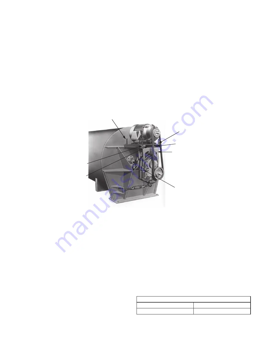
Note: Refer to photo for position of all parts before
installation.
1. Remove the two or three bolts required for mounting the
TAM Motor Mount from the reducer housing. Install the
front and rear supports (2) using the new reducer bolts (1)
supplied with the motor mount. Make sure support flanges
face output side of reducer. Tighten bolts securely.
2. Mount bottom plate (3) on supports with bolts supplied.
Insert bolts (7) from top through slotted holes. Add flat
washer, lockwasher, and nut. Hand tighten.
3. Thread two nuts (6) on each threaded stud (5) leaving
approximately 1" of stud protruding at one end. Insert
threaded stud with 1" of threads through corner holes of
bottom plate, thread a hex nut (6) on the stud and tighten
securely.
4. Slide top plate (4) over the threaded stud, making sure
center handling hole is positioned opposite input side of
reducer. Thread a hex nut (6) on the studs and tighten
securely.
WARNING: If electrical connections to motor are installed
at this time, disconnect and lock out power supply before
proceeding. Failure to observe this precaution may result
in bodily injury.
5. Locate the proper position for the motor and bolt to the top
plate. Tighten bolts securely.
6. Install motor sheave and reducer sheave as close to
motor and reducer housings as possible. Accurately align
the motor and reducer sheave by sliding bottom plate in
relation to supports. Tighten bolts (7) securely.
7. Install V-belts and tension belts by alternately adjusting
nuts (6) on the threaded studs (jackscrews). Make certain
that all bolts are securely tightened, the V-belt drive is
properly aligned and the belt guard is installed before
operating the drive.
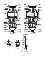
①
Rear Supports
⑦
Bolts
⑥
Hex Nuts
①
Reducer Bolts
⑤
Threaded Stud
③
Bottom Plate
④
Top Plate
GUIDELINES FOR TORQUE-ARM REDUCER
LONG-TERM STORAGE
During periods of long storage, or when waiting for delivery or
installation of other equipment, special care should be taken to
protect a gear reducer to have it ready to be in the best condition
when placed into service.
By taking special precautions, problems such as seal leakage
and reducer failure due to the lack of lubrication, improper
lubrication quantity, or contamination can be avoided. The
following precautions will protect gear reducers during periods
of extended storage:
Preparation
1. Drain the oil from the unit. Add a vapor phase corrosion
inhibiting oil (VCI-105 oil by Daubert Chemical Co.) in
accordance with Table 3.
2. Seal the unit air tight. Replace the vent plug with a standard
pipe plug and wire the vent to the unit.
3. Cover the shaft extension with a waxy rust preventative
compound that will keep oxygen away from the bare metal.
(Non-Rust X-110 by Daubert Chemical Co.)
4. The instruction manuals and lubrication tags are paper and
must be kept dry. Either remove these documents and store
them inside or cover the unit with a durable waterproof cover
which can keep moisture away.
5. Protect the reducer from dust, moisture, and other
contaminants by storing the unit in a dry area.
6. In damp environments, the reducer should be packed inside
a moisture-proof container or an envelope of polyethylene
containing a desiccant material. If the reducer is to be stored
outdoors, cover the entire exterior with a rust preventative.
When Placing the Reducer into Service
1. Assemble the vent plug into the proper hole.
2. Clean the shaft extensions with a suitable solvent.
3. Fill the unit to the proper oil level using a recommended
lubricant. The VCI oil will not affect the new lubricant.
4. Follow the installation instructions provided in this manual.
Table 3 - Quantities of VCI #105 Oil
Case Size
Quarts or Liters
TXT105,TXT205
.1
VCI #105 & #10 are interchangeable.
VCI #105 is more readily available.


