


Electromagnetic Flowmeter COPA-XT
13
4.
Start-Up
4.1
Preliminary Flowmeter System Checks
4.1.1 Checking the Flowmeter Primary COPA-XT
The start-up procedures described below are to be followed
after the assembly and installation of the flowmeter have been
completed.
The supply power is to be turned off.
•
Check the ground connections.
•
Compare connections against the Interconnection Diagram.
•
Check that the supply power values agree with the
specifications listed on the Instrument Tag.
The supply power is to be turned on!
•
After the supply power is turned on, the data in the external
EEPROM are compared to the values stored internally. If
the values are not identical an automatic upload of the data
is initiated. The converter displays the message “Primary
data loaded”. The meter is now ready for operation
•
The process information must be displayed, e.g. Page 14.
•
In order to operate the system, it is necessary to first select
or enter a few parameters. The flow range is automatically
set to 10 m/s. Enter the desired flow range for Qmax with
the appropriate engineering units. Hydraulically ideal flow
range end values lie between approx. 2-3 m/s. The current
output is set for 4-20 mA. The pulses per flow unit and the
pulse width are to be set for pulse output and the selections
in “Totalizer” submenu completed.
•
The System Zero should be checked (see 4.2)
•
After completion of the start-up procedure, call the submenu
“Store data in ext. EEPROM” in order to save the settings
which were entered during start-up. When a converter is
exchanged the EEPROM is removed from the old converter
and installed in the new one (see 4.3).
4.2
System Zero
The system zero of the flowmeter is to be set at the converter.
The fluid in the flowmeter primary must be at an absolute
standstill. It essential to assure that the flowmeter primary is
completely filled with fluid. The adjustment can be made
manually or automatically by accessing the submenu “System
zero adj.”: Select parameter using ENTER, with the arrow keys
select automatic or manual and initiate by pressing ENTER.
During the automatic zero adjustment a counter is displayed in
the 2nd line as the converter counts from 400 to 0, after which
the system zero adjustment procedure is terminated.
The adjustment takes approx. 20 seconds.
4.3
Converter Exchange
All the parameter settings are stored in an external EEPROM
installed on the display plate. When a converter is exchanged,
all the parameter settings can be uploaded into the new con-
verter by interchanging the external EEPROMs. Converter spe-
cific data are automatically updated.
!
Note:
After the configuration has been completed, all the
parameter settings should be stored in the external
EEPROM.
4.4
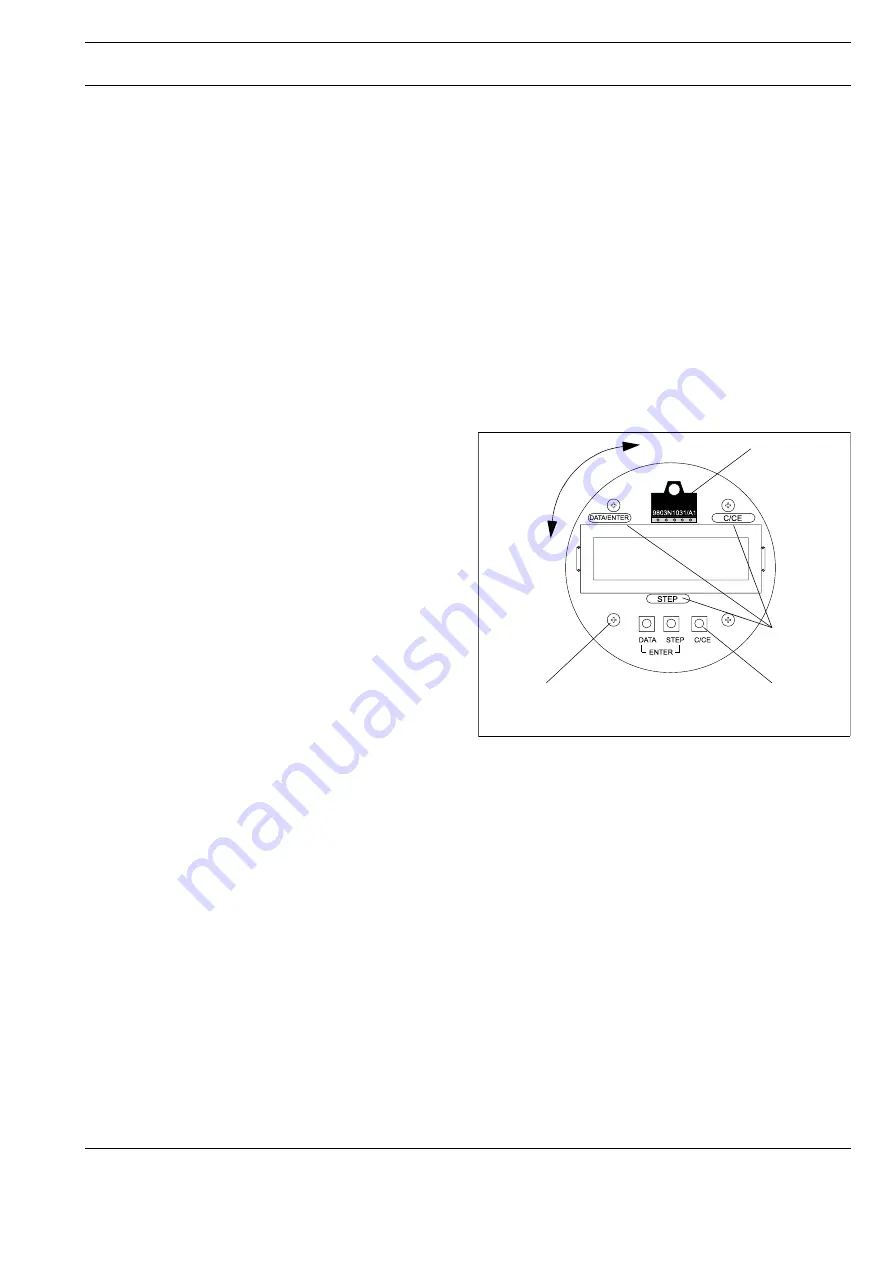
Memory Module Socket
(External EEPROM)
The socket for the ext. EEPROM is located on the front of the
display plate.
Ext. EEPROM
Data Memory
Module
Magnetic Stick
Operation
3 Keys for Direct
Operation
Rotate Display ± 90°
Plate Mounting Screws
(4 x Phillips head)
Fig. 26
Display Plate