


Single and Dual Input Analyzers for Low Level Conductivity
AX410, AX411, AX413, AX416, AX418, AX450, AX455 & AX456
Appendix B
80
IM/AX4CO Issue 11
B.3 Setting Up Three Term (PID) Control Parameters
To enable a process to be controlled satisfactorily, the following
conditions must apply:
1. The process must be capable of reaching a natural
balance with a steady load.
2. It must be possible to introduce small changes into the
system without destroying either the process or the
product.
The
Proportional Band
determines the gain of the system. (the
gain is the reciprocal of the proportional band setting, e.g. a
setting of 20% is equivalent to a gain of 5). If the proportional
band is too narrow, the control loop may become unstable and
cause the system to oscillate. With proportional band control
only, the system normally stabilizes eventually but at a value
which is offset from the set point.
The addition of
Integral Action Time
removes the offset but, if set
too short, can cause the system to go into oscillation. The
introduction of
Derivative Action Time
reduces the time required
by the process to stabilize.
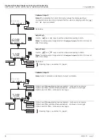
B.4 Manual Tuning
Before starting up a new process or changing an existing one:
1. Select the
Config. Control
page and ensure that
Controller
is set to
PID
- see Section 5.7.
2. Select the
PID Controller
page and set the following:
Proportional Band
-
100%
Integral Time
-
0
(off) - see Section 5.8.1
Derivative Time
-
0
(off)
3. Reduce the
Proportional Band
by 20% increments and
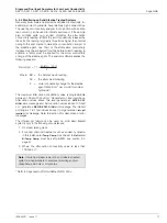
observe the response. Continue until the process cycles
continuously without reaching a stable condition (i.e. a
sustained oscillation with constant amplitude as shown in
Mode C). This is the critical point.
4. Note the cycle time 't' (Fig. B.4 Mode C) and the
Proportional Band
(critical value) setting.
5. Set
Proportional Band
to:
1.6 times the critical value (for P+D or P+I+D control)
2.2 times the critical value (for P+I control)
2.0 times the critical value (for P only control)
6. Set
Integral Time
to:
(for P+I+D control)
(for P+D control)
7. Set
Derivative Time
to:
(for P+I+D control)
(for P+D control)
The analyzer is now ready for fine tuning by small adjustments to
the P, I and D terms, after the introduction of a small disturbance
of the set point.
Note.
If the system goes into oscillation with increasing
amplitude (Fig. B.4 Mode B), reset the proportional
band to 200%. If oscillation continues as in Mode B,
increase the proportional band further until the system
ceases to oscillate.
If the system oscillates as in Fig. B.4 Mode A, or does
not oscillate, refer to step 3).
t
2
t
1.2
Fig. B.4 Control Conditions
t
8
t
12
Response Time
Pr
ocess V
ariable
Time
Mode C
Cycle Time t
Response Time
Pr
ocess V
ariable
Time
Mode B
Response Time
Pr
ocess V
ariable
Time
Mode A


