


3
—
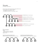
Step 4 - Connect MODBUS Networks
MODBUS networks - See Information: MODBUS Networks
• Networks may be either Singly Terminated or Doubly
Terminated.
• The Annunciator has two separate MODBUSs.
ATS MODBUS connects to ATSs - 8 max.
PC MODBUS connects a PC to Annunciators - max 32.
MODBUS connections are to a detachable terminal block.
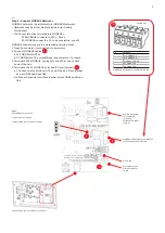
1. Open Annunciator - remove front cover screws.
2. Connect MODBUS cables :
a. ATS MODBUS to ATSs
b. PC MODBUS to PC and additional Annunciators, if present.
3. Terminate ATS MODBUS - typically in the ATS at one or both
ends of the bus.
4. Terminate the PC MODBUS at its non-PC end (typical):
a. The Annunciator at the non-PC end of the bus: Place jumper
across HDR5 positions 2&3.
b. All other Annunciators: Place jumper across HDR5 positions
1&2.
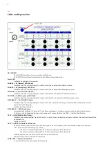
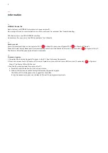
Pin
Signal
1
ATS MODBUS A
2
ATS MODBUS B
3
MODBUS RETURN
4
PC MODBUS A
5
PC MODBUS B
MODBUS Detachable Terminal Block (HDR4)
16AWG max.
HDR5
PC MODBUS Termination
Jumper 2&3: terminated
Jumper 1&2: Not terminated (shown)
Power Detachable
Terminal Block
(provided
attached to HDR3)
(Step 5)
MODBUS Detachable Terminal Block
(provided attached to HDR4)
Status LED
Factory Reset and
Firmware Update
switch
Annunciator Card - on inside of front cover
1.
3.
2.
3.
1.
3.
Содержание ATS Annunciator
Страница 10: ...10 Notes ...
Страница 11: ...11 Notes ...


