


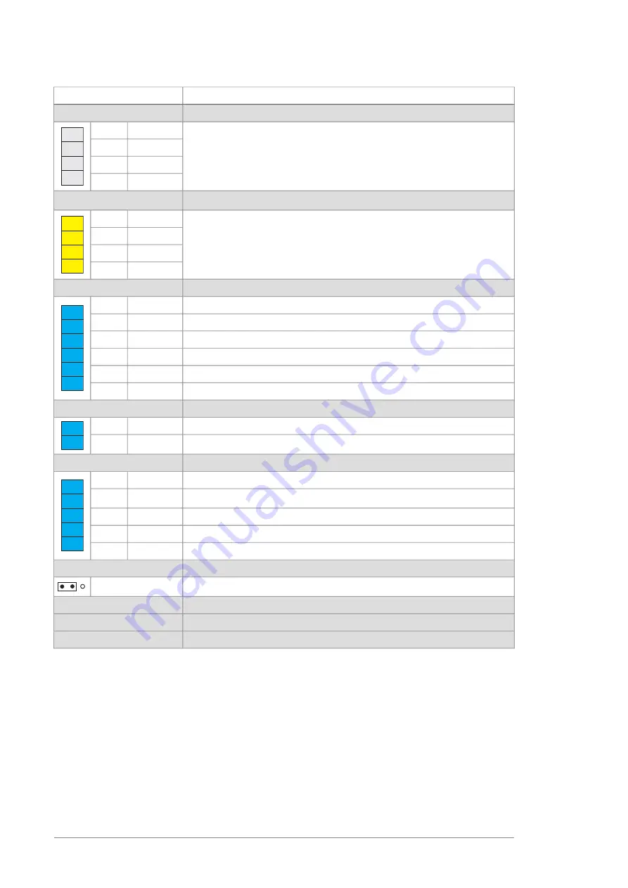
Description
Terminal
Drive-to-drive link
XD2D
Not in use by default
SHIELD
4
4
3
2
1
BGND
3
A
2
B
1
Safe torque off
6)
XSTO
Factory connection. Both circuits must be closed for the unit to start (IN1
and IN2 must be connected to OUT).
IN2
4
4
3
2
1
IN1
3
SGND
2
OUT
1
Digital inputs
XDI
(0 -> 1 = fault reset)
DI6
6
3
2
1
6
5
4
Not in use by default. Can be used for eg. earth fault monitoring.
DI5
5
Auxiliary circuit breaker fault
DI4
4
MCB feedback
(0 = main contactor/breaker open)
DI3
3
Run enable
(1 = run enable)
DI2
2
Temp fault
(0 = overtemperature)
DI1
1
Digital input/outputs
XDIO
Not in use by default
DIO2
2
2
1
Not in use by default
DIO1
1
Auxiliary voltage output
XD24
Digital input/output ground
DIOGND
5
3
2
1
5
4
+24 V DC 200 mA
7)
+24VD
4
Digital input ground
DICOM
3
+24 V DC 200 mA
+24VD
2
Not in use by default. Can be used for eg. emergency stop.
DIIL
1
Ground selection
J6
Ground selection jumper
8)
J6
Not in use in supply units
X12
Control panel connection
X13
Memory unit connection
X205
1) Default use of the signal in the control program. The use can be changed by a parameter. See also the delivery-specific
circuit diagrams.
2) Use of the signal in the control program (fixed). See also the delivery-specific circuit diagrams.
3) Current [0(4)…20 mA, R
in
= 100 ohm] or voltage [0(2)…10 V,
R
in
> 200 kohm] input selected by jumper J2. Change
of setting requires reboot of control unit.
4) Current [0(4)…20 mA, R
in
= 100 ohm] or voltage [0(2)…10 V,
R
in
> 200 kohm] input selected by jumper J1. Change
of setting requires reboot of control unit.
5) Must be set to ON when the supply unit is the first or last unit on the drive-to-drive (D2D) link. On intermediate
units, set termination to OFF.
6) This input only acts as a true Safe torque off input in inverter units. In other applications (such as a supply or brake
unit), de-energizing the IN1 and/or IN2 terminal will stop the unit but not constitute a true safety function.
7) Total load capacity of these outputs is 4.8 W (200 mA at 24 V) minus the power taken by DIO1 and DIO2.
134 The control unit
Содержание ACS880-304LC Series
Страница 1: ... ABB INDUSTRIAL DRIVES ACS880 304LC A019 diode supply modules Hardware manual ...
Страница 2: ......
Страница 4: ......
Страница 30: ...30 ...
Страница 34: ...34 ...
Страница 45: ... Kits for D8D supply modules in 400 mm Rittal VX25 or generic enclosure Cabinet construction 45 10 ...
Страница 46: ... Stage 1 Installation of common parts 46 Cabinet construction ...
Страница 47: ... Stage 2 Module installation parts Cabinet construction 47 10 ...
Страница 48: ... Stage 3 Liquid cooling system components 48 Cabinet construction ...
Страница 49: ... Stage 4 AC and DC busbar installation Cabinet construction 49 10 ...
Страница 50: ... Stage 5 AC and DC connection 50 Cabinet construction ...
Страница 51: ... Stage 6 Cabinet fan and heat exchanger Cabinet construction 51 10 ...
Страница 52: ... Stage 7 Shroud installation parts 52 Cabinet construction ...
Страница 53: ... Stage 8 Door covers and explosion exhaust kit Cabinet construction 53 10 ...
Страница 54: ...54 ...
Страница 74: ...74 ...
Страница 87: ...5 Maintenance 87 ...
Страница 88: ...6 7 8 9 9 88 Maintenance ...
Страница 92: ...92 ...
Страница 108: ...108 ...
Страница 118: ...118 ...
Страница 140: ...Liquid cooled D8D module Dimensions in mm 1 mm 0 0394 in 140 Dimension drawings ...
Страница 142: ...ZCU 14 control unit 142 Dimension drawings ...
Страница 143: ...Support plate for ZCU 14 UDZKROH 0 GRZQ UDZKROH 0 GRZQ Dimension drawings 143 ...
Страница 144: ...CIO 01 module 144 Dimension drawings ...
Страница 152: ...152 ...