


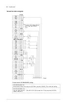


Control unit 55
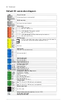
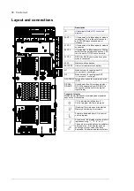
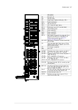
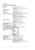
The table above shows the control connections of the DC/DC converter unit, and the
default meaning or use of the signals in the control program.
Wire sizes and tightening torques: 0.5 … 2.5 mm
2
(24…12 AWG) and 0.5 N·m (5 lbf·in) for
both stranded and solid wiring.
Notes:
1)
Use of the signal in the control program. The use is fixed and it cannot be changed by a parameter.
2)
Default use of the signal in the control program. The use can be changed by a parameter. For the delivery-
specific use, see the delivery-specific circuit diagrams.
3)
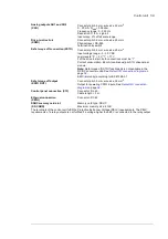
Current [0(4)…20 mA,
R
in
= 100 ohm] or voltage [0(2)…10 V,
R
in
> 200 kohm] input selected by switch AI1.
Change of setting requires reboot of control unit.
4)
Current [0(4)…20 mA,
R
in
= 100 ohm] or voltage [0(2)…10 V,
R
in
> 200 kohm] input selected by switch AI2.
Change of setting requires reboot of control unit.
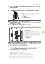
5)
Must be set to ON when the drive is the first or last unit on the drive-to-drive (D2D) link.
6)
Total load capacity of these outputs is 4.8 W (200 mA at 24 V) minus the power taken by DIO1 and DIO2.
7)
Determines whether DICOM is separated from DIOGND (ie, common reference for digital inputs floats).
DICOM = DIOGND
ON: DICOM connected to DIOGND. OFF: DICOM and DIOGND separate.
8)
The Safe torque off (STO) function is only implemented in the inverter units. When the control board is used
in the DC/DC converter unit, de-energizing IN1 or IN2 of XSTO connector only stops the operation of the unit.
This stopping is not safety-related and cannot be used in safety purposes.
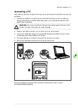
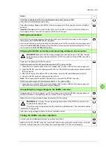
External power supply for the control unit (XPOW)
The BCU must be powered from a 24 V DC, 2 A power supply. The power supply is
connected to terminal block XPOW. A second supply can be connected to the same
terminal block for redundancy.
SDHC memory card slot
The BCU-x2 has an on-board data logger that collects real-time data from the converter to
help fault tracing and analysis. The data is stored onto the SDHC memory card inserted
into the SD CARD slot and can be analyzed by the ABB service personnel
Содержание ACS880-1607
Страница 1: ...ABB industrial drives Hardware manual ACS880 1607 DC DC converter units ...
Страница 4: ......
Страница 12: ...12 Introduction to the manual ...
Страница 34: ...34 Mechanical installation ...
Страница 40: ...40 Guidelines for planning electrical installation ...
Страница 52: ...52 Electrical installation ...
Страница 68: ...68 Start up ...
Страница 80: ...80 Maintenance 7 3 4 5 6 ...
Страница 82: ...82 Maintenance 3 4 5 6 7 8 9 9 ...
Страница 85: ...Maintenance 85 12 Install and tighten the two screws 10 11 12 ...
Страница 92: ...92 Maintenance 3 6 4 5 4 7a 7b 7b ...
Страница 93: ...Maintenance 93 9 8 8 10 11 ...
Страница 96: ...96 Maintenance 4 8 6 7 5 3 ...
Страница 97: ...Maintenance 97 9 ...
Страница 118: ...118 Dimensions Dimension drawings Frame 1 R8i bottom cable entry ...
Страница 119: ...Dimensions 119 Frame 1 R8i top cable entry ...
Страница 120: ...120 Dimensions Location and size of input terminals Frame 1 R8i bottom cable entry Frame 1 R8i top cable entry ...
Страница 122: ...www abb com drives www abb com drivespartners 3AXD50000023644 Rev B EN 2017 01 30 Contact us ...


