Actual signals and parameters
186
26.04
IR STEP-UP FREQ
Defines the frequency at which the step-up IR compensation reaches the
IR compensation used in Scalar control (
IR COMPENSATION).
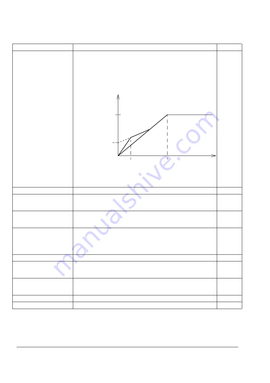
A voltage boost is used in step-up applications to achieve higher break-away
torque. Since voltage cannot be fed to the transformer at 0 Hz, special IR
compensation is used in step-up applications. Full IR compensation starts
around slip frequency. The figure below illustrates the step-up
IR compensation.
For more information, see
Sine Filters User’s Manual for ACS800 Drive
s
[3AFE68389178 (English)].
100 = 1
0...50 Hz
Frequency
26.05
HEX FIELD WEAKEN Selects whether motor flux is controlled along a circular or a hexagonal pattern
in the field weakening area of the frequency range (above 50/60 Hz). See
section
on page
OFF
The rotating flux vector follows a circular pattern. Optimal selection in most
applications: Minimal losses at constant load. Maximal instantaneous torque is
not available in the field weakening range of the speed.
0
ON
Motor flux follows a circular pattern below the field weakening point (typically
50 or 60 Hz) and a hexagonal pattern in the field weakening range. Optimal
selection in the applications that require maximal instantaneous torque in the
field weakening range of the speed. The losses at constant operation are
higher than with the selection NO.
65535
26.06
FLUX REF PTR
Selects the source for the flux reference, or sets the flux reference value.
-255.255.31 …
+255.255.31 / C.-
32768 … C.32767
Parameter index or a constant value. See parameter
for information on
the difference. The range of the flux is 25 … 140%. With constant value
settings 100% = C.10000. Typically there is no need to change this value.
100 = 1%
26.07
FS METHOD
Activates the flux correction at low frequencies, < 10% of nominal frequency,
when the torque exceeds 30%. Effective in the motoring and generating
modes.
OFF
Inactive
0
ON
Active.
1
Index
Name/Selection
Description
FbEq
U
/
U
N
(%)
f
(Hz)
Field weakening
point (FWP)
100%
26.04 IR STEP-UP
FREQ
26.03 IR
COMPENSATION
Содержание ACS 800 Series
Страница 1: ...ACS800 Firmware Manual Crane Control Program N697 ...
Страница 4: ......
Страница 26: ...Start up and control through the I O interface 26 ...
Страница 36: ...Quick start up guide 36 ...
Страница 52: ...Control panel 52 ...
Страница 105: ...Program features 105 Figure Control diagram for Shaft synchronisation executed in 20 ms ...
Страница 126: ...Program features 126 The figures below show speed limits according to different load conditions ...
Страница 128: ...Program features 128 ...
Страница 150: ...Application macros control location EXT1 EXT2 150 ...
Страница 228: ...Actual signals and parameters 228 ...
Страница 299: ...Adaptive Programming examples for crane control 299 ...
Страница 305: ...Adaptive Programming examples for crane control 305 ...
Страница 312: ...Adaptive Programming examples for crane control 312 The following figures show the previous example enlarged ...
Страница 314: ...Adaptive Programming examples for crane control 314 The following figures show the previous example enlarged ...
Страница 318: ...Analogue Extension Module 318 ...
Страница 332: ...Additional data actual signals and parameters 332 ...
Страница 333: ...DriveWindow 333 DriveWindow DriveWindow connected to the ACS800 RMIO RDCO board and channel CH3 ...
Страница 334: ...DriveWindow 334 ...
Страница 335: ...Control block diagrams 335 Control block diagrams ...
Страница 336: ...Control block diagrams 336 ...
Страница 337: ...Control block diagrams 337 ...
Страница 338: ...Control block diagrams 338 ...
Страница 340: ...www abb com drives www abb com drivespartners Contact us 3AFE68775230 Rev E EN 2012 09 25 ...


