ABB 6X1ED Скачать руководство пользователя страница 3

- 3 -

INSTALLATION

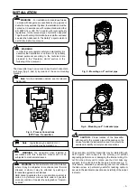
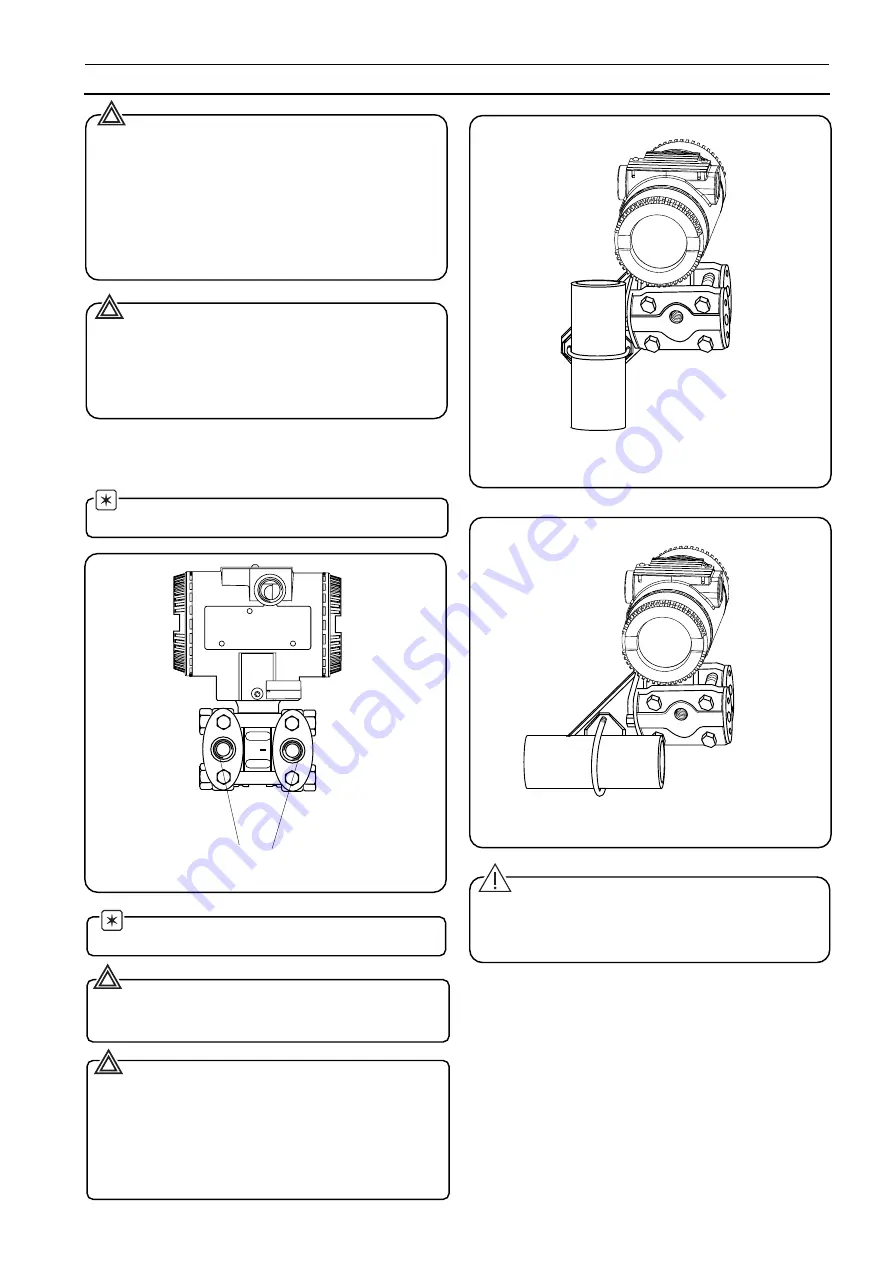
Fig. 6 - Mounting on 2" horizontal pipe

CAUTION -  Proper  location  of  the  transmitter

with respect to the process pipe will depend upon the
service for which the instrument is used. Care should be
exercised to identify correct process connections.

The secondary unit of the transmitter may be rotated through
360

°

 approx. with respect to the primary unit without

degrading performance or damaging the internal wiring. Do
not force the primary unit  to rotate;  use the 2 mm  Allen  key
supplied  to unlock and lock the tang grub screw (see Fig. 7).
This feature, obtained by unscrewing (one turn is sufficient)
the Allen screw,  is particularly useful for reaching optimum
access to the electrical connections and visibility of the output
indicator.

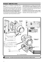
Fig. 4 - Process Connections

(Diff. Press. Transmitter)

         WARNING
In order to ensure operator safety and plant safety it is
essential that installation is carried out by suitably
trained personnel according to the technical data
provided in the "Operative Limits" section in the
following of the document.

The  transmitter  may  be mounted on a vertical or horizontal  2-
inch pipe (figg. 5 and 6) by means of the same mounting
bracket.

 Note: for other installation details  see the relevant

     Addendum.

Fig. 5 - Mounting on 2" vertical pipe

 Note:

High side may be marked H or +
Low side may be marked L or -

WARNING  - For installation in Hazardous Areas,

i.e. areas with  dangerous concentrations of e.g. gases or
dusts that may explode if ignited, the installation must be
carried out in accordance with relative standards either
EN 60079-14 or IEC 79-14 and/or with local authority
regulations, for the relevant type of protection adopted.
Together with safety information here and after enclosed
see also the Addendum for "Ex Safety"  aspects which is
part of this instruction manual.

      WARNING: The transmitter when installed in
accordance with this instruction manual will not be
subjected to mechanical stresses.

    WARNING: the transmitter should not be installed

where it may be subjected to mechanical and thermal
stresses or where it may be attached by existing or
foreseable aggressive substances.
ABB cannot guarantee that a construction material is
suited to a particular process fluid under all possible
process conditions. See also the paragraph on "Operati-
ve limits".

+

Содержание 6X1ED

Страница 1: ...Instructions Warning An instruction that draws attention to the risk of injury or death Caution An instruction that draws attention to the risk of damage to the product process or surroundings Although Warning hazards are related to personal injury and Caution hazards are associated with equipment or property damage it must be understood that operation of damaged equipment could under certain oper...

Страница 2: ...f the transducer diaphragms material fill fluid range limit and identification number Fig 1 Product identification Ref B Primary Unit Ref A Ref C Ref D Ref D Ref A DIN TYPE HOUSING BARREL TYPE HOUSING SERIAL NUMBER URL DIAPHRAGM MATERIAL FILL FLUID A Safety Marking plate ref C is fitted when the transmitter is requiredtocomplywithhazardousarearegulations e g flame proof or intrinsic safety protect...

Страница 3: ...t The transmitter may be mounted on a vertical or horizontal 2 inch pipe figg 5 and 6 by means of the same mounting bracket Note for other installation details see the relevant Addendum Fig 5 Mounting on 2 vertical pipe Note High side may be marked H or Low side may be marked L or WARNING For installation in Hazardous Areas i e areas with dangerous concentrations of e g gases or dusts that may exp...

Страница 4: ...e secondary electronics R kΩ Supply voltage min operating voltage Vdc 22 Supply voltage Total loop resistance 250 ohms 2020 25 ref 10 5 55 volts 42 4 to 20 mA and HART digital communication 620 4 to 20 mA only 600 Temperature limits C F Ambient is the operating temperature All models and sensors can withstand without damages or leakages temperatures from 40 to 85 C 40 to 185 F 20 C 4 F for Viton g...

Страница 5: ...e 0 12 mm 0 005 in per year B Concentration and Temperature Limited NR Not Recommended No Data Available Numbers indicate the maximum allowable temperature C for a generally suitable material NOTE Data of the following table are based on information from manufacturers All data is based on a temperature of 20 C 70 F unless noted otherwise Since corrosion involves many more variables than this table...

Страница 6: ... 6 CORROSION TABLE ...

Страница 7: ... 7 CORROSION TABLE ...

Страница 8: ... 8 CORROSION TABLE ...

Страница 9: ... 9 CORROSION TABLE ...

Страница 10: ... damaged if in replace WARNING Assembling flanges with incorrect fixing bolts and nuts and improper O rings can cause fracture or overstressing of bolts and release of pressurized process material Use only official spare parts and do not exceed the specified torque limits DO NOT REMOVE the O ring fitted in the sensor neck it provides the housing a degree of protection a Refit the flange fixing bol...

Страница 11: ...screw Blind cover Flange bolts Analog or digital output indicator or CoMeter Extended windowed cover Blind cover Windowed cover Microprocessor driven integral display Tang screw Terminal blocks assembly Sensor assembly Calibration screws Nameplate DISMANTLING AND REASSEMBLY ...

Страница 12: ... media D Dust dangerous media T50 C Maximum surface temperature of the transmitter enclosure with a Ta ambient temperature 40 C for Dust not Gas with a dust layer up to 50 mm depth T95 C As before for Dust for a Ta 85 C Note the number close to the CE marking of the transmitter safety label identifies the Notified Body which carries out the surveillance for the production of the transmitter The ot...

Страница 13: ...eas continuous hazard with its process part only whereas the remaining part of the transmitter i e its enclosure can be used in Zone 1 Gas only see sketch below Reason of this is the process part of the transmitter normally called primary transducer that provides inside separation elements to seal off the electrical sensor from the continuously hazardous process according to the EN50284 and EN5001...

Страница 14: ... 14 ...

Страница 15: ...conformity with the following standards EN 50 081 1 1992 Electromagnetic compatibility Generic emission standard Residential commercial and light industry according to EN55022 1995 EN 50 082 2 1995 Electromagnetic compatibility Generic immunity standard Industrial environment according to EN61000 4 2 1998 EN61000 4 3 1998 EN61000 4 4 1995 EN61000 4 5 1995 ENV50141 1993 following the provisions of ...

Страница 16: ... 16 PED600TEN Rev 1 ...

Отзывы: