5
Electromagnetic Flowmeter Converter
2.4.5 Cable Connection Area
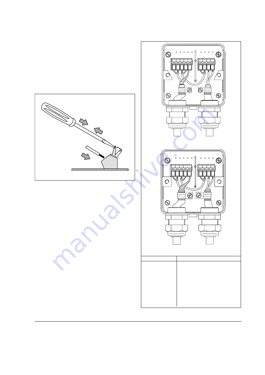
The leads of the signal cable are to be routed in the shortest
manner to the connection terminals. Loops are to be avoided,
(see Figs. 4 and 5).
Cable Connection Area with Screwless Spring
Loaded Terminals
Procedure: Press the spring element (1) and insert the stripped
lead (2).
Release the pressure (3) on the spring element
(Fig. 3).
Care should be exercised when reinstalling and tightening the
housing box cover. Check that the gasket is properly seated.
Only then is Protection Class IP 67 assured.
1
3
2
Fig.3
Cable Insertion with Screwless Spring Loaded Terminals
SE SE
3A 16 M3 M1
U- 1 2 U+ 3
3A 16
Signal Cable
Excitation Current Cable
(e.g. shielded 2x1.5 mm
2
)
Signal Cable
Excitation Current Cable
(e.g. shielded 2x1.5 mm
2
)
F
lowm
e
te
r P
rim
ar
y
wit
h
P
ream
pli
fi
e
r
Terminal Designations
Connections
1 + 2
1S + 2S
U+/U-
16
3a
3
SE
M1 + M3
Flow signal leads (red and blue)
Flow signal lead shields
Preamplifier supply voltage
over signal lead shields
Reference voltage lead (white)
Reference voltage lead shield
Inner cable shield (copper)
common potential
Outer shield (steel)
Magnetic field excitation connections
(from converter)
1S 1 2 2S 3
3A
3A
16
16
M3 M1
SE
SE
Fig.4
Connection Area for Flowmeter Primary
≤
12” (DN 300)
Содержание 50SM1000
Страница 4: ......


