


NOTE
Although a vertical installation of your meter is
best, a horizontal or sloping installation can be
very successful if the meter electrodes are ori-
ented in a horizontal plane. If either electrode is
positioned at the top, entrapped air may act as an
insulator, resulting in an unreliable measurement.
This tag highlights the installation techniques necessary for depend-
able service from your ABB Magnetic Flowmeter. By observing and
performing these operations, your meter warranty remains valid and
satisfactory performance is assured. Coverage of all recommenda-
tions given in this instruction is provided in detail within the Instruction
Manual which accompanies your meter.
METER GASKETS
Flanges must be
properly gasketed
Two gaskets are provided in the Installation Kit, as selected for the
particular application.
CONDUIT CONNECTIONS
Conduit seal fittings must be properly installed at the meter primary to
prevent condensate, that may be present in the conduit system, from
entering the customer connection box and degrading meter perform-
ance.
Conduit seals are also required to prevent the process fluid from en-
tering the electrical conduit system. This safety feature considers the
remote possibility of a primary seal failure within the flowmeter, in
which case, this secondary seal will prevent the process from enter-
ing the electrical conduit system in accordance with the National
Electrical Code (NEC) ANSI/NFPA 70, Article 501-5 (f) (3). A cable
seal and mating fittings are supplied with the meter for cables that in-
terconnect with a remotely mounted signal converter. When an inte-
grally mounted signal converter is supplied, cable seals and fittings
are provided only when the accidental submergence option has been
specified.
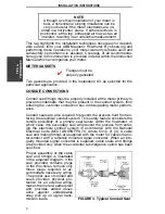
Proper assembly of the cable
seal and fittings is illustrated
in the adjacent diagram. If the
seal provided contains plugs
in the thru-holes, remove only
those plugs required to ac-
commodate necessary wiring.
The proper use of conduit and
seals provides physical pro-
tection for all external wiring,
makes the meter weatherproof
and provides added assur-
ance against undesireable
stray pick up on signal trans-
mission leads.
FIGURE 3. Typical Conduit Seal
✔
T
IPS &
T
E
CHNI
Q
U
ES
INSTALLATION INSTRUCTIONS
3


