Publication No. HRMCP9 Rev. B
PCI Mezzanine Card (PMC) 89
B • PCI Mezzanine Card (PMC)
The PCI Mezzanine Card (PMC) Interface is an additional slot for parallel mounted
add on cards. The interface is compliant to the IEEE 1386.1 specification and is based
on the electrical and logical layer of the PCI specification. Check for possible height
incompatibility in ‘Features’ and ‘Specifications’ sections of this manual. PMC Slot1
is 66/100/133 MHz PCI-X capable. PMC Slot 2 is 33 MHz/32 bit only. The user
definable I/O pins are connected to the rear IO connector on the CR9, as defined in
the PICMG 2.3 specification.
•
A 5 V key is mounted on PMC2, for 5 V compatible PMC-Cards.
•
A 3 V key is mounted on PMC1, for 3 V compatible PMC-Cards.
B.1 Electrical Characteristics
Table B-1 Electrical Characteristics
Parameter
Comment
Value
I3.3V
Max. current on 3.3 V Pins
2.1 A
c
I5V
Max. current on 5 V Pins
1.2 A
c
I+12V
Max. current on +12 V Pin
0.1 A
I-12V
a
Max. current on -12 V Pin
0.1 A
V(I/O)
b
Voltage for PCI IO
3.3 V or 5 V
P
Max. power consumption total
7.5 W
a
-12 V must be connected to the backplane
b
The appropriate key has to be mounted
c
Total power dissipation on 3.3 V and 5 V rail is 7.5 W
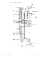
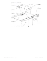
To mount a PMC board to the CR9, follow these steps:
1.
Remove CR9 from system housing
2.
Remove the front panel cover of the PC slot
3.
Take PMC from inside through front panel and push connectors together.
4.
Verify correct installation of EMC gasket
5.
Fix PMC on host boards with the four screws supplied with the PMC card.
The screws must be locked with Loctite 243 when using the CR9 in a
mechanical rough environment.
Содержание CR9 Series
Страница 24: ...24 CP9 CR9 CT9 Celeron M Pentium M Publication No HRMCP9 Rev B Figure 2 2 Handling the CR9 Board ...
Страница 77: ...Publication No HRMCP9 Rev B Transition Module CTM12 77 Figure A 1 CTM12 Component Locations ...
Страница 90: ...90 CP9 CR9 CT9 Celeron M Pentium M Publication No HRMCP9 Rev B Figure B 1 Mount PMC Board to CR9 ...


