Publication No. HRMCP9 Rev. B
Transition Module CTM12 85
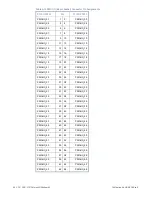
Table A-12 PMC I/O Onboard PIM Connector Pin Assignments
P7100/P7200
P7104/P7204
Pin Pin
P7100/P7200 P7104/P7204
PMCxIO_01
01
02
+12 V
b
PMCxIO_02
PMCxIO_03
03
04
PMCxIO_04
+5 V
a
PMCxIO_05
05
06
PMCxIO_06
PMCxIO_07
07
08
PMCxIO_08
PMCxIO_09
09
10
+3.3 V
a
PMCxIO_10
PMCxIO_11
11
12
PMCxIO_12
GND
PMCxIO_13
13
14
PMCxIO_14
PMCxIO_15
15
16
PMCxIO_16
PMCxIO_17
17
18
GND
PMCxIO_18
PMCxIO_19
19
20
PMCxIO_20
+5 V
a
PMCxIO_21
21
22
PMCxIO_22
PMCxIO_23
23
24
PMCxIO_24
PMCxIO_25
25
26
+3.3 V
a
PMCxIO_26
PMCxIO_27
27
28
PMCxIO_28
GND
PMCxIO_29
29
30
PMCxIO_30
PMCxIO_31
31
32
PMCxIO_32
PMCxIO_33
33
34
GND
PMCxIO_34
PMCxIO_35
35
36
PMCxIO_36
+5 V
a
PMCxIO_37
37
38
PMCxIO_38
PMCxIO_39
39
40
PMCxIO_40
PMCxIO_41
41
42
+3.3 V
a
PMCxIO_42
PMCxIO_43
43
44
PMCxIO_44
GND
PMCxIO_45
45
46
PMCxIO_46
PMCxIO_47
47
48
PMCxIO_48
PMCxIO_49
49
50
GND
PMCxIO_50
PMCxIO_51
51
52
PMCxIO_52
+5 V
a
PMCxIO_53
53
54
PMCxIO_54
PMCxIO_55
55
56
PMCxIO_56
PMCxIO_57
57
58
+3.3 V
a
PMCxIO_58
PMCxIO_59
59
60
PMCxIO_60
-12 V
a
PMCxIO_61
61
62
PMCxIO_62
PMCxIO_63
63
64
PMCxIO_64
a
+5 V, +3.3 V, –12 V nonfused supplied via CR9, max 1 A for +5 V and +3.3 V, and 100 mA for –12 V
b
+12 V supplied via the CMT12 external power connector P7700, max current 500 mA
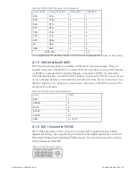
The following table lists the pin assignments of the PMC I/O signals of the 64-pin
header.
The I/O signals from PMC 1 (PMC1IO_xx) are connected to P7101 and the I/O signals
from PMC 2 (PMC2IO_xx) are connected to P7201.
Содержание CR9 Series
Страница 24: ...24 CP9 CR9 CT9 Celeron M Pentium M Publication No HRMCP9 Rev B Figure 2 2 Handling the CR9 Board ...
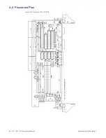
Страница 77: ...Publication No HRMCP9 Rev B Transition Module CTM12 77 Figure A 1 CTM12 Component Locations ...
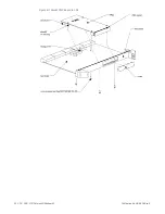
Страница 90: ...90 CP9 CR9 CT9 Celeron M Pentium M Publication No HRMCP9 Rev B Figure B 1 Mount PMC Board to CR9 ...


