Full Digital Module
Technical Guide
Factory Packaged Controls
Tulsa
Страница 1: ...Full Digital Module Technical Guide Factory Packaged Controls Tulsa...
Страница 2: ...0 PH 816 505 1100 FAX 816 505 1101 E mail mail wattmaster com Visit our web site at www orioncontrols com WattMaster Form AA FDM TGD 01G Copyright July 2016 WattMaster Controls Inc AAON Manual Part Nu...
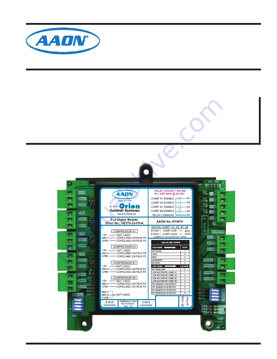
Страница 3: ...e Module OE370 23 HP1C is also installed Module Overview Figure 1 Full Digital Module The Full Digital Module is connected to the VCM X Modular Control ler using the E BUS Distribution Module OE365 23...
Страница 4: ...standard I2 C modular cable to connect with the VCM X Modular Controller VCM X Expansion Module or 12 Relay Expansion Module The Full Digital Module can also be directly connected to the VCM X Modula...
Страница 5: ...UT COM COM COM EXC EXC EXC P4 P4 P4 BK BK BK RD RD RD WH WH WH P2 P2 P2 P1 P1 P1 P3 P3 P3 P5 P5 P5 C1 C1 C1 C2 C2 C2 P6 P6 P6 SHLD OUT COM EXC P4 BK RD WH P2 P1 P3 P5 AO1 SIG 1 SIG 2 SIG 3 SIG 4 AO2 G...
Страница 6: ...r lengths and 100 and 150 foot lengths Figure 4 VCM X Modular E BUS Controller to Full Digital Module Wiring Diagram Connect To Other WattMaster Approved E BUS Expansion Module s HSSC Cable HSSC Cable...
Страница 7: ...mon Failure To Do So Will Result In Damage To The Controllers T to T R to R SHLD to SHLD Size Transformer For Correct Total Load VCM X Modular Controller 8 OE332 23E VCMX MOD A VCM X Modular E BUS Con...
Страница 8: ...e to observe polarity could result in damage to the boards Table 1 Unit Configurations Chart UNIT CONFIGURATIONS PERMUTATION SYSTEM A SYSTEM B HARDWARE VCM X WSHP CONFIGURATION Comp A1 Comp A2 Comp B1...
Страница 9: ...ital Stage 2 outputs will go to 50 and begin to modulate together If both systems are energized and they go below 30 and the SupplyAir is below the Supply Air Setpoint by the Cooling Stage Window valu...
Страница 10: ...diagnostic blink code LED It will light up and blink out diagnostic codes See Table 2 for Diagnostic Blink Code descriptions The blink code descriptions are also located on the mod ule s front cover N...
Страница 11: ...ctive R3 This LED will light up when Compressor B1 is enabled and will stay lit as long as Compressor B1 is active R4 This LED will light up when Compressor B2 is enabled and will stay lit as long as...
Страница 12: ...If the COMM LED does not blink then communications have not been established Check the connection between the VCM X Modular Con troller the VCM X Modular E BUS Controller the E BUS Distribution Modul...
Страница 13: ...e and Voltage Chart for R410A Refrigerant testing Table 4 The chart shows a temperature range from 20 F to 80 F For troubleshooting pur poses the DC Voltage readings are also listed with their corresp...
Страница 14: ...Digital Room Sensor And Or Digital CO Sensor 2 Warning 24 VAC Must Be Connected So That All Ground Wires Remain Common Failure To Do So Will Result In Damage To The Controllers T to T R to R SHLD to...
Страница 15: ...COMM GND VDC 485 DRV 24VAC GND PWR YS102308 REV 1 I2C TO COMM DIST BOARD OUTPUT Modular Cable Connect To VCM X Modular Controller HSSC Cable Connect To E BUS Distribution Module Connect To Other Watt...
Страница 16: ...2425 So Yukon Ave Tulsa OK 74107 2728 Ph 918 583 2266 Fax 918 583 6094 AAON Manual Part No R84500 WattMaster Manual Form No AA FDM TGD 01G www aaon com...