background image

MODGAS-XWR-1 Technical Guide


                                                          NOTES

37

Содержание OE377-26-00060-1

Страница 1: ...OE377 26 00060 1 AAON Part No V82790 MODGAS XWR Controller Technical Guide Factory Packaged Controls ...

Страница 2: ...PLAY SCREENS 22 TROUBLESHOOTING 29 APPENDIX A Supply Air Temperature Sensor Guide 34 APPENDIX B MODGAS XWR 1 Replacement of MODGAS XWR 36 PART DESCRIPTION PART NUMBER MODGAS XWR 1 Controller V82790 MODGAS XWR Controller V20780 VCCX2 Controller V87900 VCB X Controller V28940 VCM X Modular E BUS Controller V07150 12 Relay E BUS Expansion Module R69180 Supply Air Temperature Sensor P87140 AAON Inc 24...

Страница 3: ...The controller can be used as a stand alone unit or be connected to a 12 Relay E BUS Expansion Module stand alone only or VCM X E BUS I2 C Controller VCB X Controller or VCCX2 Controller using a modular cable The MODGAS XWR Controller can be configured for one 1 modulat ing valve with one ignitor as one stage two 2 modulating valves with one ignitor as one stage two 2 modulating valves with two ign...

Страница 4: ...at all ground wires remain common Failure to follow this procedure can result in damage to the module and connected devices 5 All wiring is to be in accordance with local and national electrical codes and specifications 6 Check all wiring leads at the terminal block for tightness Be sure that wire strands do not stick out and touch adjacent terminals Confirm that all transducers required for your sy...

Страница 5: ...AAON Unit Controller Figure 9 page 12 This configuration is used to control one modulating valve which must be placed on the gas valve 1 header attached to Heat 1 Relay NOTE Up to 3 additional fixed heat stages can be used by using Heat Relays 2 3 4 below and up to 12 more additional fixed stages can be added by using the 12 Relay E BUS Expansion Module Figure 8 page 11 If using an MHGRV X Controller...

Страница 6: ... modulating gas valves one on each header in which the first valve is modulating stage 1 valve 1 header and the second valve is modulating stage 2 valve 2 header The first valve is attached to Heat Relay 1 and the second valve is at tached to Heat Relay 2 NOTE Up to 2 additional fixed heat stages can be used by using Heat Relays 3 4 below and up to 12 more additional fixed stages can be added by using...

Страница 7: ... tion thus creating four modulating valves as 2 stages This configuration operates as Stand Alone Figure 4 below or communicating with an AAON Unit Controller Figure 12 page 15 NOTE Up to 2 additional fixed heat stages can be used by using Heat Relays 3 4 below and up to 12 more additional fixed stages can be added by using the 12 Relay E BUS Expansion Module Figure 8 page 11 If using a MHGRV X Cont...

Страница 8: ...ach header in which the first and second valves operate together for one modulating stage Both valves are connected to Heat 1 Relay NOTE Up to 3 additional fixed heat stages can be used by using Heat Relays 2 3 4 below and up to 12 more additional fixed stages can be added by using the 12 Relay E BUS Expansion Module Figure 8 page 11 If using an MHGRV X Controller along with the MODGAS XWR Controller...

Страница 9: ...ion thus creating four modulating valves as one stage This configuration operates as Stand Alone Figure 6 below or communicating with an AAON Unit Controller Figure 14 page 17 NOTE Up to 3 additional fixed heat stages can be used by using Heat Relays 2 3 4 below and up to 12 more additional fixed stages can be added by using the 12 Relay E BUS Expansion Module Figure 8 page 11 If using a MHGRV X Con...

Страница 10: ...is used to control two modulating gas valves one on each header in which the first and second valves operate together for one modulating stage One valve is connected to Heat 1 Relay and the second valve is connected to Heat 2 Relay NOTE Up to 2 additional fixed heat stages can be used by using Heat Relays 3 4 below and up to 12 more additional fixed stages can be added by using the 12 Relay E BUS Exp...

Страница 11: ...he 12 Relay E BUS Expansion Module to operate the Stand Alone setting in the LCD Configuration Screens must be set to Forced If communication is lost to the 12 Relay E BUS Expansion Module the 12 Relay E BUS Expansion Module will turn off its relays and the MODGAS XWR Controller will alarm and fall back to using only its onboard stages If communications is restored the MODGAS XWR Controller will beg...

Страница 12: ...valve 1 header attached to Heat 1 Relay For VCM X Controllers use an I2 C Cable connecting to the appropriate I2 C port on the controller For all other controllers use an E BUS cable connecting to an E BUS port on the controller NOTE Up to 3 additional fixed heat stages can be used by using Heat Relays 2 3 4 below If additional fixed stages are required these should be configured and wired to the AAO...

Страница 13: ...ating stage One valve is connected to Heat 1 Relay and the second valve is connected to Heat 2 Relay For VCM X Controllers use an I2 C Cable connecting to the appropriate I2 C port on the controller For all other controllers use an E BUS cable connecting to an E BUS port on the controller NOTE Up to 2 additional fixed heat stages can be used by using Heat Relays 3 4 below If additional fixed stages ...

Страница 14: ...one on each header in which the first valve is modulating stage 1 valve 1 header and the second valve is modulating stage 2 valve 2 header The first valve is attached to Heat Relay 1 and the second valve is at tached to Heat Relay 2 For VCM X Controllers use an I2 C Cable connecting to the appropriate I2 C port on the controller For all other controllers use an E BUS cable connecting to an E BUS por...

Страница 15: ...nd Figure 12 below is the Secondary por tion thus creating four modulating valves as two stages This configuration operates as Stand Alone Figure 4 page 7 or communicating with an AAON Unit Controller NOTE Up to 3 additional fixed heat stages can be used by using Heat Relays 3 4 below If additional fixed stages are required these should be configured and wired to the AAON Unit Controller s relays NOTE...

Страница 16: ...ng gas valves one on each header in which the first and second valves operate together for one modulating stage Both valves are connected to Heat 1 Relay NOTE Up to 3 additional fixed heat stages can be used by using Heat Relays 2 3 4 below If additional fixed stages are required these should be configured and wired to the AAON Unit Controller s relays For VCM X Controllers use an I2 C Cable connectin...

Страница 17: ...and Figure 14 below is the Secondary por tion thus creating four modulating valves as one stage This configuration operates as Stand Alone Figure 6 page 9 or communicating with an AAON Unit Controller NOTE Up to 3 additional fixed heat stages can be used by using Heat Relays 3 4 below If additional fixed stages are required these should be configured and wired to the AAON Unit Controller s relays NOTE...

Страница 18: ...f Flame alarm Proof of Ignition 2 PO IGN2 The Proof of Ignition input is activated by a 24VAC signal supplied from the Ignition Module to enable the modulating Gas Valve 2 If the flame does not ignite the Ignition Module will turn off this enable The MODGAS XWR Controller will then turn on the No Proof of Flame alarm Communicating Outputs Gas Valve Output 1 This communicating output will control the...

Страница 19: ...mber of Heat Stages installed in the unit note that if there are two heat units to be operated in a primary secondary arrangement this is considered 1 stage of heat The fifth configuration screen selects the configuration The options for Stand Alone operation are 1 1 modulating 1 ignitor 1 stage 2 2 modulating 2 ignitors 1 stage 3 2 modulating 2 ignitors 2 stages which allows a secondary MODGAS XWR 1...

Страница 20: ... speed 2V2IGN2S The PID loop runs every 10 seconds and determines the modulation percentage for the one variable valve Then the valve moves to the correct position Only after the stage up delay requirement has been met will the board stage up and open the second variable valve After this both valves will move simultaneously to the same percent modulations During the modulation sequence if the valv...

Страница 21: ...but keep in mind that bringing one below the low speed cutoff and another above it will cause low speed relay difficulties Forcing stages 2 4 on forces Heat Relays 2 4 on respectively 2V1IGN1S Forcing stage 1 on forces Heat Relay 1 on and the next screen allows the option to select the modulation percentage since both valves are one stage they both modulate at the same percentage Forcing stages 2 4 o...

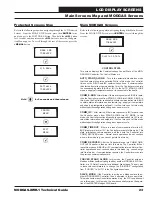
Страница 22: ...to turn Valve Force Mode off ENTER Use the Enter key to move through screens within Main Menu categories Also use this key to save setpoints and configuration changes Main Screens Map Refer to the following map when navigating through the LCD Main Screens The first screen is an initialization screen To scroll through the rest of the screens press the MENU button MGAS XWR 1086vXXX STATUS MENU ALARMS M...

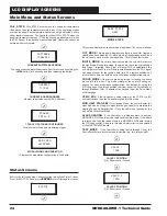
Страница 23: ...is a loss of communication for either E BUS master or slave or I2C the Controller moves into this mode This state re initializes communications and then puts the Controller into COMM_RECOVER mode Normal board operations do not continue when in this mode e g you cannot go into Heat mode COMM_RECOVER After the Controller moves into COMM_TIME OUT the Controller is then put into this mode The Controll...

Страница 24: ...he Controller is being tested for the VCM X via I2C communications then the Controller moves into this mode MOD HEAT STAGE After Ignition Mode the unit will enter the Heat Mode and will begin to modulate the gas valve s to maintain the Heating Supply Air Setpoint SAT Once the call for heat goes away the unit will leave the Heat Mode SLAVE_HEATING If the Controller is a Modbus slave to another MODG...

Страница 25: ...t Screens From the SETPOINT Screen press ENTER to scroll through the screens and change setpoints Use the UP and DOWN arrow keys to change your selections Then press ENTER to save the new setpoint WARNING The ENTER key must be pressed after changing setpoints for your entries to be saved for subsequent power ups NOTE When the MODGAS XWR is operating in Communi cations Mode these setpoints screens ...

Страница 26: ...the Force Mode back off or after 10 minutes of no keypad input the valve will go to zero and the relays will turn off STAGE 2 FORCE ON OFF DISABLED V2 POSITION X FORCE VALVE 2 PERCENTAGE This screen only appears when Valve 2 Force is on Press the UP button to turn the Force Mode on Press the DOWN button to turn the Force Mode off If the screen says disabled on off selection is not possible Press the U...

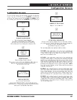
Страница 27: ...d to Heat 1 Relay Additional stages may be added to Heat Relays 2 3 4 or off board if in a communication mode 2V1IGN1S Valve configuration used to control two modulating gas valves one on each header in which the first and second valves operate together for one modulating stage Both valves are connected to Heat 1 Relay therefore an additional fixed stage may be added on board at the Heat 2 Relay Addit...

Страница 28: ...steps Default is 70 STG UP DLY 1 TO 10 m STAGE UP DELAY Range is 1 to 10 minutes Default is 3 IGN RTRY DLY 1 60 m IGNITION RETRY DELAY Range is 1 60 minutes Default is 30 STG DOWN DLY 1 TO 10 m STAGE DOWN DELAY Range is 1 or 10 minutes Default is 1 LOSAT SU 0 45 F LOW SUPPLY AIR TEMPERATURE START UP Range is 0 45ºF Default is 40ºF If the Supply Air Temperature is 40 adjustable or less the stage up...

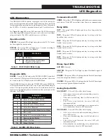
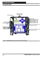
Страница 29: ... Failure 10 Stage 2 Failure Table 4 ALARM LED Blink Codes Communication LED COMM This yellow LED will light up and blink when communications are detected If this LED never blinks then there is no communication Relay LEDs RLY1 This green LED will light up and stay lit as long as the Fan relay is active RLY2 This green LED will light up and stay lit as long as the Low Speed Fan relay is active RLY3 ...

Страница 30: ...TROUBLESHOOTING MODGAS XWR 1 Technical Guide 30 Figure 16 MODGAS XWR Controller LED Locations and Descriptions Troubleshooting ...

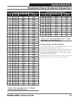
Страница 31: ...GND on the Main Controller communicating mode Remove SAT and GND wiring from MODGAS XWR and ohm sensor out this may indicate open or failed wiring Refer to chart on pages 30 31 of this guide for readings Verify the SAT OPTIONS jumper settings on the MODGAS XWR for the Supply Air Temperature Sensor Fail Mode SAT Cutoff Remove SAT and GND wiring from the MODGAS XWR and ohm sensor out this may indica...

Страница 32: ... 0 60552 2 83 10 12 2 52500 2 77 15 9 4 45902 2 71 20 6 7 40147 2 64 25 3 9 35165 2 57 30 1 1 30805 2 49 35 1 6 27140 2 41 40 4 4 23874 2 33 45 7 2 21094 2 24 50 10 0 18655 2 15 52 11 1 17799 2 11 54 12 2 16956 2 08 56 13 3 16164 2 04 58 14 4 15385 2 00 60 15 6 14681 1 96 62 16 7 14014 1 93 64 17 8 13382 1 89 66 18 9 12758 1 85 Temperature to Resistance Voltage Chart Temp F Temp C Resistance Ohms ...

Страница 33: ... 40147 4 095 25 3 9 35165 3 982 30 1 1 30805 3 862 35 1 6 27140 3 737 40 4 4 23874 3 605 45 7 2 21094 3 470 50 10 0 18655 3 330 52 11 1 17799 3 275 54 12 2 16956 3 217 56 13 3 16164 3 160 58 14 4 15385 3 100 60 15 6 14681 3 042 62 16 7 14014 2 985 64 17 8 13382 2 927 66 18 9 12758 2 867 68 20 0 12191 2 810 69 20 6 11906 2 780 70 21 1 11652 2 752 71 21 7 11379 2 722 72 22 2 11136 2 695 73 22 7 1087...

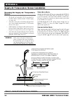
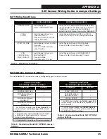
Страница 34: ... to these instructions prior to testing the unit or else the modulating valve will not control properly and may damage your equipment Figure 17 Supply Air Temperature Sensor Installation Stand Alone Mode In Stand Alone Mode the SATSensor is connected to the MODGAS X Controller If in Stand Alone Mode the MODGAS X Controller is used in conjunction with a Stand Alone MHGRV Controller the SAT sensor i...

Страница 35: ...r VCCX2 Connect to VCB X or VCCX2 using E BUS cable Install Supply Air Sensor in VCB X or VCCX2 Connect to VCB X or VCCX2 using E BUS cable VCM X SA RNE Install Supply Air Sensor in Main Controller Connect to Main Controller using I2 C cable Install Supply Air Sensor in Main Controller Connect to Main Controller using I2 C cable VCM VAV CAV MUA MUA II MUA IID Install Supply Air Sensor in MODGAS XW...

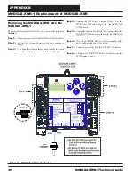
Страница 36: ...rature Sensor needs to remain installed on whatever controller it is currently on Figure 18 MODGAS XWR 1 Controller Step 4 Unplug the TB2 Input Terminal Block from the MODGAS XWR and replug it into the MODGAS XWR 1 board Step 5 Unplug the Ignition blocks and Valve headers from the MODGAS XWR and replug them into the MODGAS XWR 1 board Step 6 Wire the MODGAS XWR 1 relays according to the valve confi...

Страница 37: ...MODGAS XWR 1 Technical Guide NOTES 37 ...

Страница 38: ...NOTES MODGAS XWR 1 Technical Guide 38 ...

Страница 39: ...MODGAS XWR 1 Technical Guide NOTES 39 ...

Страница 40: ...2425 South Yukon Ave Tulsa OK 74107 2728 Ph 918 583 2266 Fax 918 583 6094 AAON Part No V73440 Rev 01B Printed in the USA November 2018 AAON All Rights Reserved ...

Отзывы: