E m b e d d e d C o n t r o l l e r
T K S - G 2 0 - L N 0 5
Chapter 2 Quick Installation Guide
2 - 9
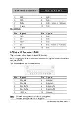
3 RXD+
4 N/C
5 TXD+
6 N/C
7
RXD-
8
N/C / +5 Volt. / (+12 Volt.)
9 Ground
10
N/C
RS-485 Mode
Pin
Signal Pin
Signal
1 TXD-
2 N/C
3 N/C
4 N/C
5 TXD+
6 N/C
7
N/C
8
N/C / +5 Volt. / (+12 Volt.)
9 Ground
10
N/C
2.7 Digital I/O Connector (CN26)
This connector offers 4-pair of digital I/O function.
BIOS using the I2C Bus to read/write internal DIO registers and the Serial Bus
address is 0x6E.
The pin definitions are illustrated below:
Pin
Signal Pin
Signal
1 DIO_IN0
2 DIO_IN1
3 DIO_IN2
4 DIO_IN3
5 DIO_OUT0
6 DIO_OUT1
7 DIO_OUT2
8 DIO_OUT3
9 +3.3
Volt.
10
Ground
Note:
The max. rating of Pin 1 ~ Pin 8 is 3.3V@8mA
The max. rating of Pin 9 is [email protected]
Содержание TKS-G20-LN05
Страница 10: ...Embedded Controller T K S G 2 0 L N 0 5 Chapter 1 General Information 1 1 General Chapter 1 Information ...
Страница 18: ...Embedded Controller T K S G 2 0 L N 0 5 Chapter 2 Quick Installation Guide 2 4 Solder Side ...
Страница 31: ...Embedded Controller T K S G 2 0 L N 0 5 Chapter 3 AMI BIOS Setup 3 1 AMI Chapter 3 BIOS Setup ...
Страница 34: ...Embedded Controller T K S G 2 0 L N 0 5 Chapter 4 Driver Installation 4 1 Driver Chapter 4 Installation ...
Страница 46: ...Embedded Controller T K S G 2 0 L N 0 5 Appendix B DIO B 1 DIO Appendix B ...


