background image


Chapter 4 – Driver Installation & Touchscreen Settings 


96 

In

du

str

ial Mo

du

la

r T

ou

ch

 P

an

el

 PC


OM
NI

-B

T S

eries


3.


Run patch.bat as administrator 


Содержание OMNI-3105-BT

Страница 1: ...Last Updated March 30 2018 OMNI BT Series Industrial Modular Touch Panel PC With Intel Bay Trail Platform User s Manual 2nd Ed...

Страница 2: ...provided in this manual is intended to be accurate and reliable However the original manufacturer assumes no responsibility for its use or for any infringements upon the rights of third parties that...

Страница 3: ...gistered trademark of Microsoft Corp Intel Pentium Celeron and Xeon are registered trademarks of Intel Corporation Core Atom are trademarks of Intel Corporation ITE is a trademark of Integrated Techno...

Страница 4: ...product please make sure the following items have been shipped Item Quantity OMNI BT Series Panel PC panel size from 10 4 21 5 1 Product CD with drivers 1 Phoenix Power connector 1 If any of these it...

Страница 5: ...such as detailed descriptions and explanations on the product s hardware and software features if any its specifications dimensions jumper connector settings definitions and driver installation instr...

Страница 6: ...ng on the system s hardware 6 No connections should be made when the system is powered as a sudden rush of power may damage sensitive electronic components 7 If the device is not to be used for a long...

Страница 7: ...containers 18 If any of the following situations arises please the contact our service personnel i Damaged power cord or plug ii Liquid intrusion to the device iii Exposure to moisture iv Device is n...

Страница 8: ...ger of explosion if the battery is incorrectly replaced Replace only with the same or equivalent type recommended by the manufacturer Dispose of used batteries according to the manufacturer s instruct...

Страница 9: ...Preface IX Industrial Modular Touch Panel PC OMNI BT Series China RoHS Requirements CN AAEON Panel PC Workstation Pb Hg Cd Cr VI PBB PBDE O SJ T 11363 2006 X SJ T 11363 2006...

Страница 10: ...xternal Connections O O O O O O Chassis O O O O O O CPU RAM O O O O O O Hard Disk O O O O O O LCD O O O O O O Optical Drive O O O O O O Touchscreen O O O O O O PSU O O O O O O O The quantity of poison...

Страница 11: ...Modules 19 1 2 1 USB COM LAN Module 19 1 2 2 Dual LAN Module 19 1 2 3 MiniCard and SIM Card Module 20 1 2 4 RS 232 422 485 Module 20 1 2 5 Isolated RS 232 422 485 Module 21 1 2 6 Digital I O Module 21...

Страница 12: ...LPC Debug Port CN4 41 2 3 3 Battery Connector CN6 42 2 3 4 Cfast Connector CN10 42 2 3 5 Board to Board Connector CN11 43 2 3 6 Panel Size Select CN15 17 inch LCD 45 2 3 7 LVDS Backlight Connector CN...

Страница 13: ...ced IDE Configuration 72 3 4 3 Advanced USB Configuration 73 3 4 4 Advanced Hardware Monitor 74 3 4 5 Advanced Power Management 75 3 4 6 Advanced Super IO Management 76 3 4 6 1 Super IO Management Ser...

Страница 14: ...gramming 102 A 1 Watchdog Timer Initial Program 103 Appendix B I O Information 105 B 1 I O Address Map 106 B 2 Memory Address Map 108 B 3 IRQ Mapping Chart 109 Appendix C OMNI COM Module UART Setting...

Страница 15: ...Industrial Modular Touch Panel PC OMNI BT Series Chapter 1 Chapter 1 Product Specifications...

Страница 16: ...to 4 GB N2807 Ethernet Intel 10 100 100Base TX RJ 45 x 2 Side I O USB 3 0 Type A x 1 USB 2 0 Type A x 3 SMA antenna hole x 1 HDMI x 1 CFast x 1 Bottom I O DB 9 for RS 485 422 232 x 1 10 100 1000Base...

Страница 17: ...rature 10 C 60 C with industrial grade device with 0 5 m s air flow according to IEC68 2 14 CPU N2807 10 C 55 C with industrial grade device with 0 5 m s air flow according to IEC68 2 14 CPU J1900 Use...

Страница 18: ...Chapter 1 Product Specifications 4 Industrial Modular Touch Panel PC OMNI BT Series Power Supply DC Input 9 30 V...

Страница 19: ...n W x H x D 280 x 239 x 59 mm 11 x 9 4 x 2 3 Carton Dimension W x H x D 415 x 391 x 179 mm 16 3 x 15 4 x 7 Gross Weight 3 6 kg 7 9 lb LCD Display Type 10 4 TFT LCD Max Resolution 800 x 600 Max Colors...

Страница 20: ...Chapter 1 Product Specifications 6 Industrial Modular Touch Panel PC OMNI BT Series Touchscreen P CAP Type Projected capacitive touch screen Light Transmission 90 3 Lifetime...

Страница 21: ...W x H x D 329 x 288 x56 mm 13 x 11 3 x 2 2 Carton Dimension W x H x D 530 x 445 x 200 mm 20 9 x 17 5 x 7 9 Gross Weight 5 kg 11 lb LCD Display Type 12 1 TFT LCD Max Resolution 1024 x 768 Max Colors 1...

Страница 22: ...Chapter 1 Product Specifications 8 Industrial Modular Touch Panel PC OMNI BT Series Touchscreen P CAP Type Projected capacitive touch screen Light Transmission 90 3 Lifetime...

Страница 23: ...D 369 x 314 x 58 mm 14 5 x 12 4 x 2 3 Carton Dimension W x H x D 522 x 478 x 262 mm 20 6 x 18 8 x 10 3 Gross Weight 6 35 kg 14 lb LCD Display Type 15 TFT LCD Max Resolution 1024 x 768 Max Colors 16 7...

Страница 24: ...Chapter 1 Product Specifications 10 Industrial Modular Touch Panel PC OMNI BT Series Touchscreen P CAP Type Projected capacitive touch screen Light Transmission 85 Lifetime...

Страница 25: ...420 x 265 x 60 mm 16 5 x 10 4 x 2 4 Carton Dimension W x H x D 530 x 445 x 200 mm 20 9 x 17 5 x 7 9 Gross Weight 6 65 kg 14 7 lb LCD Display Type 15 6 TFT LCD Max Resolution 1366 x 768 Max Colors 16...

Страница 26: ...Chapter 1 Product Specifications 12 Industrial Modular Touch Panel PC OMNI BT Series Touchscreen P CAP Type Projected capacitive touch screen Light Transmission 90 3 Lifetime...

Страница 27: ...x H x D 400 x 370 x 59 mm 15 7 x 14 6 x 2 3 Carton Dimension W x H x D 522 x 490 x 262 mm 20 6 x 19 3 x 10 3 Gross Weight 7 2 kg 15 9 lb LCD Display Type 17 TFT LCD Max Resolution 1280 x 1024 Max Colo...

Страница 28: ...Chapter 1 Product Specifications 14 Industrial Modular Touch Panel PC OMNI BT Series Touchscreen P CAP Type Projected capacitive touch screen Light Transmission 85 Lifetime...

Страница 29: ...x H x D 460 8 x 410 x 62 7 mm 18 1 x 16 1 x 2 5 Carton Dimension W x H x D 661 x 496 x 200 mm 26 x 19 5 x 7 9 Gross Weight 8 8 kg 19 4 lb LCD Display Type 19 TFT LCD Max Resolution 1280 x 1024 Max Col...

Страница 30: ...Chapter 1 Product Specifications 16 Industrial Modular Touch Panel PC OMNI BT Series Touchscreen P CAP Type Projected capacitive touch screen Light Transmission 85 Lifetime...

Страница 31: ...D 550 x 373 x 53 mm 21 7 x 14 7 x 2 1 Carton Dimension W x H x D 670 x 525 x 200 mm 26 4 x 20 7 x 7 9 Gross Weight 8 9 kg 19 6 lb LCD Display Type 21 5 TFT LCD Max Resolution 1920 x 1080 Max Colors 1...

Страница 32: ...Chapter 1 Product Specifications 18 Industrial Modular Touch Panel PC OMNI BT Series Touchscreen P CAP Type Projected capacitive touch screen Light Transmission 85 Lifetime...

Страница 33: ...pand its base capabilities Please refer to the sections below for their features Note The interface between the CPU box and the module is through PCIe signal 1 2 1 USB COM LAN Module Features USB 2 0...

Страница 34: ...dustrial Modular Touch Panel PC OMNI BT Series 1 2 3 MiniCard and SIM Card Module Features MiniCard x 2 SIM Card x 2 1 2 4 RS 232 422 485 Module Features RS 232 422 485 x 4 Selectable by jumper Note Y...

Страница 35: ...1 2 5 Isolated RS 232 422 485 Module Features Isolated RS 232 422 485 x 4 Selectable by jumper 2k Vdc Isolation Note You need to install the COM Port driver 1 2 6 Digital I O Module Features Digital...

Страница 36: ...Support plug and play after installing driver reboot 1 2 9 HMS Module Features 10 100 Ethernet x 2 Note a Not include HMS I O card b Europe Limitation 1 2 10 COM x 4 DIO x 16 Module Features Isolated...

Страница 37: ...cations 23 Industrial Modular Touch Panel PC OMNI BT Series 1 2 11 Wifi 802 11 b g n Module Features Support 802 11 b g n Support BT 3 0 1 2 12 RS 485 422 232 x 2 Module Features RS 485 422 232 x 2 Se...

Страница 38: ...Industrial Modular Touch Panel PC OMNI BT Series Chapter 2 Chapter 2 Hardware Information...

Страница 39: ...Chapter 2 Hardware Information 25 Industrial Modular Touch Panel PC OMNI BT Series 2 1 Dimensions 2 1 1 Dimensions Main Panels OMNI 3105 BT...

Страница 40: ...Chapter 2 Hardware Information 26 Industrial Modular Touch Panel PC OMNI BT Series OMNI 3125 BT...

Страница 41: ...Chapter 2 Hardware Information 27 Industrial Modular Touch Panel PC OMNI BT Series OMNI 3155 BT...

Страница 42: ...Chapter 2 Hardware Information 28 Industrial Modular Touch Panel PC OMNI BT Series OMNI 2155...

Страница 43: ...Chapter 2 Hardware Information 29 Industrial Modular Touch Panel PC OMNI BT Series OMNI 3175 BT...

Страница 44: ...Chapter 2 Hardware Information 30 Industrial Modular Touch Panel PC OMNI BT Series OMNI 3195 BT...

Страница 45: ...Chapter 2 Hardware Information 31 Industrial Modular Touch Panel PC OMNI BT Series OMNI 2215 BT...

Страница 46: ...Chapter 2 Hardware Information 32 Industrial Modular Touch Panel PC OMNI BT Series 2 1 2 Dimensions OMNI Modules USB CAN LAN Module Dual LAN Module MiniCard SIM Card Module RS 232 422 485 Module...

Страница 47: ...Chapter 2 Hardware Information 33 Industrial Modular Touch Panel PC OMNI BT Series Isolated RS 232 422 485 Module Digital I O Module Audio Module HMS Module...

Страница 48: ...Chapter 2 Hardware Information 34 Industrial Modular Touch Panel PC OMNI BT Series COM x 4 DIO x 16 Module COM x 2 Module COM5 COM3 COM4 COM6 COM4 COM3...

Страница 49: ...Chapter 2 Hardware Information 35 Industrial Modular Touch Panel PC OMNI BT Series 2 1 3 Dimensions Cables Touch and Panel Select Cable LVDS Cable...

Страница 50: ...ease refer to the table below for all of the system s jumpers that you can configure for your application Label Function JP1 Clear CMOS JP3 AT ATX mode selection JP4 LVDS Port Backlight Lightness Cont...

Страница 51: ...lear CMOS JP1 Normal Default Clear CMOS 2 2 2 AT ATX Mode Selection JP3 ATX Default AT 2 2 3 LVDS Port Backlight Lightness Control Mode Selection JP4 VR Mode PWM Mode Default 2 2 4 LVDS Inverter Volta...

Страница 52: ...Information 38 Industrial Modular Touch Panel PC OMNI BT Series 2 2 5 Touch Selection JP8 Pin Function 1 2 4 8 wire 2 3 5 wire Default 2 2 6 COM2 12V 5V Ring Selection JP9 Pin Function 1 2 12 V 3 4 Ri...

Страница 53: ...Battery connector CN9 SIM socket CN10 CFast connector CN11 Board to board connector CN15 Panel size select CN17 LVDS backlight connector CN18 Mini PCIe slot mSATA select CN19 SATA power connector 5V C...

Страница 54: ...NC 4 GND 5 NC 6 1 5V 7 PCIE_CLK_REQ 8 UIM_PWR 9 GND 10 UIM_DATA 11 PCIE_REF_CLK 12 UIM_CLK 13 PCIE_REF_CLK 14 UIM_RST 15 GND 16 UIM_VPP 17 NC 18 GND 19 NC 20 W_DISABLE 21 GND 22 PCIE_RST 23 PCIE_RX 24...

Страница 55: ...2 V3 3A 2 3 2 LPC Debug Port CN4 Pin Pin Name Signal Type Signal Level 1 LAD0 I O 3 3V 2 LAD1 I O 3 3V 3 LAD2 I O 3 3V 4 LAD3 I O 3 3V 5 3 3V PWR 3 3V 6 LFRAME IN 7 LRESET OUT 3 3V 8 GND GND 9 LCLK OU...

Страница 56: ...tery Connector CN6 Pin Signal 1 RTC 2 GND 2 3 4 Cfast Connector CN10 Pin Pin Name Signal Type Signal Level S1 GND GND S2 SATA_TX DIFF S3 SATA_TX DIFF S4 GND GND S5 SATA_RX DIFF S6 SATA_RX DIFF S7 GND...

Страница 57: ...2 3 5 Board to Board Connector CN11 Pin Pin Name Signal Type Signal Level 1 V5A PWR 5V 2 V5A PWR 5V 3 V5A PWR 5V 4 V5A PWR 5V 5 V3 3A PWR 3 3V 6 V3 3A PWR 3 3V 7 V3 3A PWR 3 3V 8 EX_PLT_RST out 9 V12...

Страница 58: ...21 SMBUS_CLK BI 22 USB_DP2 DIFF 23 GND GND 24 GND GND 25 P2_REFCLKN DIFF 26 P2_RXN DIFF 27 P2_REFCLKP DIFF 28 P2_RXP DIFF 29 GND GND 30 GND GND 31 P2_TXN DIFF 32 CLK_PCIE_EXIO_N DIFF 33 P2_TXP DIFF 34...

Страница 59: ...ignal 1 DIO0 GND 2 DIO1 GND 3 DIO2 5V 4 DIO3 5 DIO4 6 DIO5 7 DIO6 8 DIO7 9 5V 10 GND 2 3 7 LVDS Backlight Connector CN17 Pin Signal Pin Signal 1 VDD 2 BKL_CTL 3 GND 4 GND 5 BKL_EN 2 3 8 Mini PCIe Slot...

Страница 60: ...F 14 NC 15 GND GND 16 NC PWR 17 NC 18 GND GND 19 NC 20 W_DISABLE OUT 3 3V 21 GND GND 22 PCIE_RST OUT 3 3V 23 PCIE_RX MSATA_RX DIFF 24 3 3VSB PWR 3 3V 25 PCIE_RX MSATA_RX DIFF 26 GND GND 27 GND GND 28...

Страница 61: ...ch Panel PC OMNI BT Series 37 GND GND 38 USB_D DIFF 39 3 3VSB PWR 3 3V 40 GND GND 41 3 3VSB PWR 3 3V 42 NC 43 GND GND 44 NC 45 NC 46 NC 47 NC 48 1 5V PWR 1 5V 49 NC 50 GND GND 51 NC 52 3 3VSB PWR 3 3V...

Страница 62: ...l Level 1 GND GND 2 SATA_TX DIFF 3 SATA_TX DIFF 4 GND GND 5 SATA_RX DIFF 6 SATA_RX DIFF 7 GND GND 2 3 11 LVDS Connector CN21 Pin Signal Pin Signal 1 BKL_EN 2 BKL_CTL 3 NA 4 GND 5 NA 6 V1 5S 7 NA 8 UIM...

Страница 63: ...DATA2 25 LVDSB_DATA3 26 LVDSB_DATA3 27 LVDSVCC 28 GND 29 LVDSB_CLK 30 LVDSB_CLK 2 3 12HDMI Connector CN22 Pin Pin Name Signal Type Signal Level 1 TMDS_DAT2 DIFF 2 GND GND 3 TMDS_DAT2 DIFF 4 TMDS_DAT1...

Страница 64: ...lar Touch Panel PC OMNI BT Series 17 GND GND 18 5V PWR 5V 19 HPLG_DETECT IN 2 3 13Touchscreen Connector CN29 Pin Signal Pin Signal 1 GND 2 TOP EXCITE 3 BOTTOM EXCITE 4 LEFT EXCITE 5 RIGHT EXCITE 6 TOP...

Страница 65: ...Modular Touch Panel PC OMNI BT Series 2 3 14LAN1 Connector CN37 Pin Signal Pin Signal 1 MDI0 2 MDI0 3 MDI1 4 MDI2 5 MDI2 6 MDI1 7 MDI3 8 MDI3 2 3 15LAN2 Connector CN38 Pin Signal Pin Signal 1 MDI0 2 M...

Страница 66: ...MNI BT Series 2 3 16DC in CN39 Pin Signal Pin Signal 1 9 30V 2 GND 3 EARTH_GND 2 3 17COM2 Connector CN40 RS 232 Pin Signal Pin Signal 1 DCD 2 RXD 3 TXD 4 DTR 5 GND 6 DSR 7 RTS 8 CTS 9 RI RS 422 Pin Si...

Страница 67: ...7 N C 8 N C 9 N C 2 3 18Remote Switch Connector CN43 Pin Signal Pin Signal 1 EXT_PWRBTN 2 GND 2 3 19Combo connector CN45 Pin Signal Pin Signal 1 USB_CM_P7 2 V5_TOUCH 3 USB_CM_P7 4 GND 5 GND 6 Y 7 VCC_...

Страница 68: ...Chapter 2 Hardware Information 54 Industrial Modular Touch Panel PC OMNI BT Series 23 NC 24 NC...

Страница 69: ...l Modular Touch Panel PC OMNI BT Series 2 4 Assembling Modules To install a module Step 1 Insert the connector to the OMNI slot by the side of the PCB box Step 2 Secure with the screws provided The mo...

Страница 70: ...er 2 Hardware Information 56 Industrial Modular Touch Panel PC OMNI BT Series To detach a module Step 1 Remove the screws from the module Step 2 Remove the module The module is detached from the main...

Страница 71: ...formation 57 Industrial Modular Touch Panel PC OMNI BT Series 2 5 Installing the Hard Disk Drive 1 Put the rubber provided onto the holes of the bracket 2 Place the HDD onto the bracket and secure wit...

Страница 72: ...on 58 Industrial Modular Touch Panel PC OMNI BT Series 3 Hook the setup on to the bar above the PCB board as shown below Secure it with the screw provided Users are advised to use storage devices prov...

Страница 73: ...59 Industrial Modular Touch Panel PC OMNI BT Series 2 6 Installing DRAM To install DRAM remove the HDD and HDD bracket and insert the RAM module as shown below Users are advised to use DRAM modules p...

Страница 74: ...ation 60 Industrial Modular Touch Panel PC OMNI BT Series 2 7 Mount the OMNI onto the wall Step 1 Glue the waterproof rubber along back side of the panel Step 2 Screw the provided mounting brackets in...

Страница 75: ...Chapter 2 Hardware Information 61 Industrial Modular Touch Panel PC OMNI BT Series Step 3 use screws to secure the panel onto the wall with the wall mount brackets...

Страница 76: ...ion 62 Industrial Modular Touch Panel PC OMNI BT Series 2 8 Assemble the OMNI panel and the CPU Box The left photo shows the LCD Kit and the right photo shows BOXER Kit Step 1 Plug connectors into con...

Страница 77: ...Chapter 2 Hardware Information 63 Industrial Modular Touch Panel PC OMNI BT Series Step 2 Assemble the panel and CPU Box Step 3 Slide the CPU Box into the panel and tighten them with screws...

Страница 78: ...Chapter 2 Hardware Information 64 Industrial Modular Touch Panel PC OMNI BT Series The assembling process is completed...

Страница 79: ...pter 2 Hardware Information 65 Industrial Modular Touch Panel PC OMNI BT Series 2 9 P CAP Touch Screen Operating 1 Always touch the screen with finger pads 2 The force of finger should be lower than 1...

Страница 80: ...Industrial Modular Touch Panel PC OMNI BT Series Chapter 3 Chapter 3 AMI BIOS Setup...

Страница 81: ...routines check the current system configuration against the values stored in the CMOS memory If they do not match an error message will be outputted in which case you will need to run the BIOS setup p...

Страница 82: ...etained when the power is turned off To enter BIOS Setup press Del or F2 immediately while your computer is powering up The function for each interface can be found below Main Date and time can be set...

Страница 83: ...Chapter 3 AMI BIOS Setup 69 Industrial Modular Touch Panel PC OMNI BT Series 3 3 Setup Submenu Main...

Страница 84: ...Chapter 3 AMI BIOS Setup 70 Industrial Modular Touch Panel PC OMNI BT Series 3 4 Setup Submenu Advanced...

Страница 85: ...T Series 3 4 1 Advanced CPU Configuration Options summary Intel Virtualization Technology Disabled Enabled Optimal Default Failsafe Default Enable or Disable Intel Virtualization Technology EIST Disab...

Страница 86: ...Chapter 3 AMI BIOS Setup 72 Industrial Modular Touch Panel PC OMNI BT Series 3 4 2 Advanced IDE Configuration Options summary SATA Mode IDE Mode AHCI Mode Optimal Default Failsafe Default...

Страница 87: ...ed USB Configuration Options summary Legacy USB Support Enabled Optimal Default Failsafe Default Disabled Auto Enables BIOS Support for Legacy USB Support When enabled USB can be functional in legacy...

Страница 88: ...Chapter 3 AMI BIOS Setup 74 Industrial Modular Touch Panel PC OMNI BT Series 3 4 4 Advanced Hardware Monitor...

Страница 89: ...s Last State Optimal Default Failsafe Default Power On Power Off Select power state when power is re applied after a power failure Wake on Ring Enable Optimal Default Failsafe Default Disable Enable o...

Страница 90: ...Chapter 3 AMI BIOS Setup 76 Industrial Modular Touch Panel PC OMNI BT Series 3 4 6 Advanced Super IO Management Note Serial Port 5 8 are activated with OMNI Module...

Страница 91: ...Enable or Disable Serial Port COM Possible Use Automatic Settings Optimal Default Failsafe Default IO 2F8 IRQ 3 IO 3F8 IRQ 4 Select an optimal setting for IO device Mode RS232 250K bps Optimal Defaul...

Страница 92: ...Options summary Use This Device Disabled Enabled Optimal Default Failsafe Default Enable or Disable Serial Port COM Possible Use Automatic Settings Optimal Default Failsafe Default IO 2D0 IRQ 7 IO 2C0...

Страница 93: ...ptional Options summary Use This Device Disabled Enabled Optimal Default Failsafe Default En Disable Serial Port COM Possible Use Automatic Settings Optimal Default Failsafe Default IO 2C0 IRQ 7 IO 2D...

Страница 94: ...tional Options summary Use This Device Disabled Enabled Optimal Default Failsafe Default En Disable Serial Port COM Possible Use Automatic Settings Optimal Default Failsafe Default IO 2B0 IRQ 10 IO 2B...

Страница 95: ...tional Options summary Use This Device Disabled Enabled Optimal Default Failsafe Default En Disable Serial Port COM Possible Use Automatic Settings Optimal Default Failsafe Default IO 2B8 IRQ 10 IO 2B...

Страница 96: ...Chapter 3 AMI BIOS Setup 82 Industrial Modular Touch Panel PC OMNI BT Series 3 5 Setup submenu Chipset...

Страница 97: ...Chapter 3 AMI BIOS Setup 83 Industrial Modular Touch Panel PC OMNI BT Series 3 5 1 Chipset North Bridge...

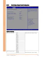
Страница 98: ...BT Series 3 5 1 1 North Bridge Display Control Configuration Options summary DVMT Pre Allocated 64M Optimal Default Failsafe Default 96M 128M 160M 192M 224M 256M 288M 320M 352M 384M 416M 448M 480M 51...

Страница 99: ...ptimal Default Failsafe Default HDMI LVDS LVDS Disabled Enabled Optimal Default Failsafe Default Panel Type Selection Auto Optimal Default Failsafe Default Manual OMNI Panel Type Unknown Auto detect O...

Страница 100: ...Chapter 3 AMI BIOS Setup 86 Industrial Modular Touch Panel PC OMNI BT Series 3 5 2 Chipset South Bridge Options summary Audio Controller Disabled Optimal Default Failsafe Default Enabled...

Страница 101: ...d does not provide access to many of the features in the Setup utility Select the password you wish to set press Enter to open a dialog box to enter your password you can enter no more than six letter...

Страница 102: ...s summary Quiet Boot Disabled Enabled Optimal Default Failsafe Default En Disable showing boot logo Option ROM Messages Force BIOS Optimal Default Failsafe Default Keep Current Set display mode for Op...

Страница 103: ...Chapter 3 AMI BIOS Setup 89 Industrial Modular Touch Panel PC OMNI BT Series 3 8 Boot BBS Priorities...

Страница 104: ...Chapter 3 AMI BIOS Setup 90 Industrial Modular Touch Panel PC OMNI BT Series 3 9 Setup submenu Exit...

Страница 105: ...Industrial Modular Touch Panel PC OMNI BT Series Chapter 4 Chapter 4 Drivers Installation Touchscreen Settings...

Страница 106: ...vers 1 Open the Step 1 Chipset folder and select your OS 2 Open the SetupChipset exe file in the folder 3 Follow the instructions 4 Drivers will be installed automatically Step 2 Install Graphics Driv...

Страница 107: ...structions 4 Drivers will be installed automatically Step 6 Install PenMount Touch 6000 Series Driver Resistive touchscreen only 1 Open the STEP 6 PenMount Touch 6000 folder followed by Setup exe 2 Fo...

Страница 108: ...Chapter 4 Driver Installation Touchscreen Settings 94 Industrial Modular Touch Panel PC OMNI BT Series For Windows 7 1 Change User Account Control settings to Never notify...

Страница 109: ...Chapter 4 Driver Installation Touchscreen Settings 95 Industrial Modular Touch Panel PC OMNI BT Series 2 Reboot and log in as administrator...

Страница 110: ...Chapter 4 Driver Installation Touchscreen Settings 96 Industrial Modular Touch Panel PC OMNI BT Series 3 Run patch bat as administrator...

Страница 111: ...er 4 Driver Installation Touchscreen Settings 97 Industrial Modular Touch Panel PC OMNI BT Series For Windows 8 1 Open the Apps Screen right click on the Command Prompt tile and select Run as Administ...

Страница 112: ...sides by entering cd folder eg if the file is in a folder named abc enter cd abc 4 You are now at the folder where the file is located Enter the patch bat to open and install the drivers If your file...

Страница 113: ...ver Optional folder and select Win10_32_64 2 Open the Setup exe file in the folder 3 Follow the instructions 4 Drivers will be installed automatically Step 7 2 Install USB to UART Driver 1 Open the US...

Страница 114: ...Modular Touch Panel PC OMNI BT Series 4 2 PCAP Dual Monitor Touch Settings When two panels are used they can set to be the primary and secondary display The instruction below shows how this can be don...

Страница 115: ...Modular Touch Panel PC OMNI BT Series 2 Go to Tablet PC Settings in Control Panel Under Display options select the primary display from step 1 Apply the changes and exit Do NOT calibrate the screen on...

Страница 116: ...Industrial Modular Touch Panel PC OMNI BT Series Appendix A Appendix A Watchdog Timer Programming...

Страница 117: ...nit 0 second 1 minute Watchdog Enable 0x07 Note9 0xF5 Note10 5 Note11 1 Note12 0 Disable 1 Enable Timeout Status 0x07 Note13 0xF5 Note14 6 Note15 1 1 Clear timeout status Output Mode 0x07 Note16 0xF5...

Страница 118: ...Val This parameter is represented from Note8 define byte EnableLDN This parameter is represented from Note9 define byte EnableReg This parameter is represented from Note10 define byte EnableBit This p...

Страница 119: ...Industrial Modular Touch Panel PC OMNI BT Series Appendix B Appendix B I O Information...

Страница 120: ...Appendix B I O Information 106 Industrial Modular Touch Panel PC OMNI BT Series B 1 I O Address Map Note There is no PS 2 interface on the OMNI BT series hence the exclamation marks...

Страница 121: ...Appendix B I O Information 107 Industrial Modular Touch Panel PC OMNI BT Series...

Страница 122: ...Appendix B I O Information 108 Industrial Modular Touch Panel PC OMNI BT Series B 2 Memory Address Map...

Страница 123: ...Appendix B I O Information 109 Industrial Modular Touch Panel PC OMNI BT Series B 3 IRQ Mapping Chart...

Страница 124: ...Appendix B I O Information 110 Industrial Modular Touch Panel PC OMNI BT Series...

Страница 125: ...Appendix B I O Information 111 Industrial Modular Touch Panel PC OMNI BT Series...

Страница 126: ...Industrial Modular Touch Panel PC OMNI BT Series Appendix C Appendix C OMNI COM Module UART Setting...

Страница 127: ...I COM Module UART Setting 113 Industrial Modular Touch Panel OMNI BT Series C 1 9741215513 PER T497 RS 232 422 485 x 2 I O module Signal type USB Jumper setting for RS232 422 R85 EX RS 232 Jumper sett...

Страница 128: ...Appendix C OMNI COM Module UART Setting 114 Industrial Modular Touch Panel OMNI BT Series EX RS 422 Jumper setting as bellow...

Страница 129: ...C OMNI COM Module UART Setting 115 Industrial Modular Touch Panel OMNI BT Series EX RS 485 Jumper setting as bellow RS 232 Pin Define Pin Signal Pin Signal 1 DCD 2 RXD 3 TXD 4 DTR 5 GND 6 DSR 7 RTS 8...

Страница 130: ...COM Module UART Setting 116 Industrial Modular Touch Panel OMNI BT Series RS 422 Pin Define Pin Signal Pin Signal 1 TXD 2 TXD 3 RXD 4 RXD 5 GND 6 N C 7 N C 8 N C 9 N C RS 485 Pin Define Pin Signal Pin...

Страница 131: ...Appendix C OMNI COM Module UART Setting 117 Industrial Modular Touch Panel OMNI BT Series C 2 9741215513 PER T371 OMNI COM x 2 USB x 2 LAN x 1 I O module Signal type USB COM3 COM4 RS232 RS485 RS422...

Страница 132: ...rial Modular Touch Panel OMNI BT Series RS 485 Jumper setting as bellow RS 232 Jumper Setting switch position switch position switch position switch position RS 232 Pin Define Pin Signal Pin Signal 1...

Страница 133: ...ial Modular Touch Panel OMNI BT Series RS 422 Jumper setting as bellow RS 422 Jumper Setting switch position switch position switch position switch position RS 422 Pin Define Pin Signal Pin Signal 1 T...

Страница 134: ...ART Setting 120 Industrial Modular Touch Panel OMNI BT Series RS 485 Jumper setting as bellow RS 485 Jumper Setting switch position switch position switch position switch position RS 485 Pin Define Pi...

Страница 135: ...Touch Panel OMNI BT Series C 3 9741215516 RS 232 422 485 x 4 Signal type USB Jumper setting for RS232 422 R85 RS 232 RS422 RS485 JP1 1 2 JP6 1 2 JP9 1 2 JP12 1 2 JP1 1 2 JP1 3 4 JP6 1 2 JP6 3 4 JP9 1...

Страница 136: ...Appendix C OMNI COM Module UART Setting 122 Industrial Modular Touch Panel OMNI BT Series EX RS 232 Jumper setting as bellow RS 422 Jumper setting as bellow...

Страница 137: ...x C OMNI COM Module UART Setting 123 Industrial Modular Touch Panel OMNI BT Series RS 485 Jumper setting as bellow RS 232 Pin Define Pin Signal Pin Signal 1 DCD 2 RXD 3 TXD 4 DTR 5 GND 6 DSR 7 RTS 8 C...

Страница 138: ...COM Module UART Setting 124 Industrial Modular Touch Panel OMNI BT Series RS 422 Pin Define Pin Signal Pin Signal 1 TXD 2 TXD 3 RXD 4 RXD 5 GND 6 N C 7 N C 8 N C 9 N C RS 485 Pin Define Pin Signal Pin...

Страница 139: ...h Panel OMNI BT Series C 4 9741215517 Isolation RS 232 422 485 x 4 Signal type USB Jumper setting for RS232 422 R85 RS 232 RS422 RS485 JP1 1 2 JP6 1 2 JP9 1 2 JP12 1 2 JP1 1 2 JP1 3 4 JP6 1 2 JP6 3 4...

Страница 140: ...Appendix C OMNI COM Module UART Setting 126 Industrial Modular Touch Panel OMNI BT Series EX RS 232 Jumper setting as bellow RS 422 Jumper setting as bellow...

Страница 141: ...x C OMNI COM Module UART Setting 127 Industrial Modular Touch Panel OMNI BT Series RS 485 Jumper setting as bellow RS 232 Pin Define Pin Signal Pin Signal 1 DCD 2 RXD 3 TXD 4 DTR 5 GND 6 DSR 7 RTS 8 C...

Страница 142: ...COM Module UART Setting 128 Industrial Modular Touch Panel OMNI BT Series RS 422 Pin Define Pin Signal Pin Signal 1 TXD 2 TXD 3 RXD 4 RXD 5 GND 6 N C 7 N C 8 N C 9 N C RS 485 Pin Define Pin Signal Pin...

Страница 143: ...215518 PER T432 Isolation RS 232 422 485 x 4 DIO x 16 I O Module Signal type USB PCB back side for jumper setting Jumper setting for RS232 422 R85 RS 232 RS422 RS485 JP1 1 2 JP6 1 2 JP9 1 2 JP12 1 2 J...

Страница 144: ...Appendix C OMNI COM Module UART Setting 130 Industrial Modular Touch Panel OMNI BT Series EX Setting for RS 232 RS 422 Jumper setting as bellow...

Страница 145: ...NI COM Module UART Setting 131 Industrial Modular Touch Panel OMNI BT Series RS 485 Jumper setting as bellow Pin Define RS 232 Pin Define Pin Signal Pin Signal 1 DCD 2 RXD 3 TXD 4 DTR 5 GND 6 DSR 7 RT...

Страница 146: ...ustrial Modular Touch Panel OMNI BT Series RS 422 Pin Define Pin Signal Pin Signal 1 TXD 2 TXD 3 RXD 4 RXD 5 GND 6 N C 7 N C 8 N C 9 N C RS 485 Pin Define Pin Signal Pin Signal 1 D 2 D 16 bit DIO Sett...

Страница 147: ...strial Modular Touch Panel OMNI BT Series DIO 16BIT CN15 Pin Signal Pin Signal 1 DIO1 2 DIO2 3 DIO3 4 DIO4 5 DIO5 6 DIO6 7 DIO7 8 DIO8 9 5V 10 GND CN16 Pin Signal Pin Signal 1 DIO9 2 DIO10 3 DIO11 4 D...

Страница 148: ...ager in Windows 2 Find the target COM device of Fintek Serial which comes from OMNI COM Module 3 Right click and select Properties 4 Switch to page Advance Setting 5 Select the target UART Mode RS232...

Отзывы: