background image

H a l f - s i z e   C P U   C a r d  

H S B - 8 1 1 P


                   Chapter 1 General Information 


1-7


Display 


Chip: Intel

®

 82852GM   


Memory size: 

Shared memory up to 64MB   

I/O 


Enhanced IDE Interface

ATA100 x 2 channels 

(supports two ATAPI 

devices for each channel) 


FDD Interface: 

Standard FDD port x 1   

(support up to 2 floppy 

devices) 


Serial Ports: 

Two COM ports: Internal Pin 


Header, External D-sub x2 


COM 1: RS-232 


COM 2: RS-232/422/485 


Parallel Port: 

Support SPP/EPP/ECP 


mode 


K/B & Mouse connector: Mini-DIN for PS/2 K/B and   


Mouse connector x 1   

Internal keyboard pin 

header x   1 


IrDA


IrDA Tx/Rx header x 1 


USB


5 x 2 pin header x 1; 


USB 2.0 ports x 5; 

 Type-A 

connector 


onboard x 3 

Содержание HSB-811P

Страница 1: ...Half size CPU Card H S B 8 1 1 P HSB 811P Onboard Intel Celeron M 600 non cache Processors Half size CPU Card With DDR Ethernet CompactFlash Mini PCI HSB 811P Manual Rev A 2nd Ed May 2009...

Страница 2: ...this manual is intended to be accurate and reliable However the original manufacturer assumes no responsibility for its use or for any infringements upon the rights of third parties that may result fr...

Страница 3: ...Inc CompactFlash is a trademark of the Compact Flash Association Intel Pentium M and Celeron M are trademarks of Intel Corporation Microsoft Windows is a registered trademark of Microsoft Corp ITE is...

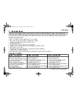
Страница 4: ...n shipped 1 HSB 811P CPU Card 1 Floppy Cable 1 ATA 100 Cable 1 USB Cable 1 PS 2 Keyboard Mouse Cable 1 Serial Parallel Cable 1 Serial Cable 1 ATX Cable 1 Quick Installation Guide 1 CD ROM for manual i...

Страница 5: ...2 4 List of Jumpers 2 7 2 5 List of Connectors 2 7 2 6 Setting Jumpers 2 9 2 7 Clear CMOS JP1 2 10 2 8 LCD Voltage Selection JP2 2 10 2 9 Front Panel Connector FP1 2 10 2 10 Front Panel Connector FP2...

Страница 6: ...etup 3 1 System Test and Initialization 3 2 3 2 Award BIOS Setup 3 3 Chapter 4 Driver Installation 4 1 Installation 4 3 Appendix A Programming The Watchdog Timer A 1 Programming A 2 A 2 ITE8712F HX Wa...

Страница 7: ...Half size CPU Card H S B 8 1 1 P Chapter 1 General Information 1 1 General Chapter 1 Information...

Страница 8: ...11P will complete AAEON s product line in Penitum 4 level short card series and provide customers higher performance and better quality product HSB 811P is a high performance with low power consumptio...

Страница 9: ...r peripheral devices Industrial applications will benefit from the five USB 2 0 ports by three pin headers and on Type A connector onboard offering 480 Mbps high speed efficiency and value without com...

Страница 10: ...o 2GB Integrated AGP 4X 2D 3D Graphics Accelerator LVDS Support Integrated AC97 Codec Audio Daughter Board Optional Supports One 10 100 1000Base T Ethernet 10 100 GbE Optional Supports Ultra ATA100 Co...

Страница 11: ...Intel 82801DB ICH4 ITE 8712F HX Ethernet 10 100Mb or 10 100 1000Mb LAN optional RJ 45 x 1 Intel 82562EZ or 82541GI controller System Memory 200 pins 2 5V DDR SODIMM Socket x 2 total up 2GB support DDR...

Страница 12: ...ontroller Integrated on Intel 82852GM LVDS output supports dual display Floppy Drive Interface Standard FDDx1 supports up to two floppy devices Audio Daughter Board Realtek ALC655 AC97 Codec MIC in Li...

Страница 13: ...h channel FDD Interface Standard FDD port x 1 support up to 2 floppy devices Serial Ports Two COM ports Internal Pin Header External D sub x2 COM 1 RS 232 COM 2 RS 232 422 485 Parallel Port Support SP...

Страница 14: ...Half size CPU Card H S B 8 1 1 P Chapter 1 General Information 1 8 OS Support Request Windows 98SE Windows 2000 Pro Windows XP Pro Linux Red Hat Windows CE net By demand Windows XP Embedded By demand...

Страница 15: ...k Installation Chapter 2 Guide Notice The Quick Installation Guide is derived from Chapter 2 of user manual For other chapters and further installation instructions please refer to the user manual CD...

Страница 16: ...hile the power is on because a sudden rush of power can damage sensitive electronic components Always ground yourself to remove any static charge before touching the board Modern electronic devices ar...

Страница 17: ...8 1 1 P Chapter 2 Quick Installation Guide 2 3 2 2 Location of Connectors and Jumpers Component Side VGA1 IDE1 IDE2 USB1 USB2 USB3 LAN1 CN4 USB4 COM2 COM1 LPT1 FP2 FP1 FDD1 ATX2 ATX1 CN1 FAN1 JP2 CN3...

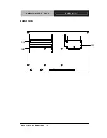
Страница 18: ...Half size CPU Card H S B 8 1 1 P Chapter 2 Quick Installation Guide 2 4 Solder Side CFD1 DIMM0 DIMM1...

Страница 19: ...ter 2 Quick Installation Guide 2 5 2 3 Mechanical Drawings Component Side 118 01 3 99 3 99 177 98 3 02 4 01 98 5 19 48 16 51 184 99 122 4 45 0 51 12 27 30 48 13 84 9 32 1 6 14 5 6 5 13 4 6 27 12 55 14...

Страница 20: ...Half size CPU Card H S B 8 1 1 P Chapter 2 Quick Installation Guide 2 6 Solder Side 184 99 16 51 98 5 4 01 3 02 177 98 3 99 3 99 118 01 122 4 45 12 27 30 48 13 84 9 32...

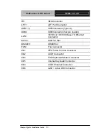
Страница 21: ...age Selection 2 5 List of Connectors The board has a number of connectors that allow you to configure your system to suit your application The table below shows the function of each board s connectors...

Страница 22: ...nector Type A USB4 USB Connector 5x2 pin header LAN1 10 100 or 100 1000 Base TX Ethernet Connector MPCI1 Mini PCI Slot DIMM0 1 DIMM Slot FAN1 Fan Connector CN1 ATX Power Control Connector CN2 AC97 Con...

Страница 23: ...them To close a jumper you connect the pins with the clip To open a jumper you remove the clip Sometimes a jumper will have three pins labeled 1 2 and 3 In this case you would connect either pins 1 a...

Страница 24: ...ector FP1 Pin Signal Pin Signal 1 Power On Button 2 Reset Switch 3 Power On Button 4 Reset Switch 5 IDE LED 6 Power LED 7 IDE LED 8 Power LED 2 10 Front Panel Connector FP2 Close Pin 5 7 Internal Buzz...

Страница 25: ...5 Serial Port Connector COM2 Pin Signal Pin Signal 1 DCD 422TXD 485DATA 2 RXD 422RXD 3 TXD 422TXD 485DATA 4 DTR 422RXD 5 GND 6 DSR 7 RTS 8 CTS 9 RI 10 N C 2 13 IrDA Connector IR1 Pin Signal 1 5V 2 N C...

Страница 26: ...DATA6 16 GND 17 DATA7 18 GND 19 ACK 20 GND 21 BUSY 22 GND 23 PE 24 GND 25 SELECT 26 N C 2 15 USB Connector USB4 Pin Signal Pin Signal 1 5V 2 GND 3 USBD1 4 GND 5 USBD1 6 USBD2 7 GND 8 USBD2 9 GND 10 5V...

Страница 27: ...7 GND 8 5V 9 LOCK 10 3 3V 2 19 LVDS Channel Connector CN3 Pin Signal Pin Signal 1 BKLEN 2 BKLCTL 3 PPVCC 4 GND 5 CH1_CLK 6 CH1_CLK 7 PPVCC 8 GND 9 CH1_TX0 10 CH1_TX0 11 CH1_TX1 12 CH1_TX1 13 CH1_TX2...

Страница 28: ...ide 2 14 2 20 PS 2 Keyboard Mouse Connector CN4 Pin Signal 1 KB_DATA 2 MS_DATA 3 GND 4 5V 5 KB_CLK 6 MS_CLK 2 21 Internal Keyboard Connector CN5 Pin Signal 1 KB_CLK 2 KB_DATA 3 N C 4 GND 5 5V 2 22 LAN...

Страница 29: ...ze CPU Card H S B 8 1 1 P Chapter 2 Quick Installation Guide 2 15 Below Table for China RoHS Requirements AAEON Main Board Daughter Board Backplane Pb Hg Cd Cr VI PBB PBDE O SJ T 11363 2006 X SJ T 113...

Страница 30: ...Half size CPU Card H S B 8 1 1 P Chapter 3 Award BIOS Setup 3 1 Chapter Award 3 BIOS Setup...

Страница 31: ...e F1 key to continue the boot up sequence System configuration verification These routines check the current system configuration against the values stored in the CMOS memory If they do not match the...

Страница 32: ...MOS Features Use this menu for basic system configuration Date time IDE etc Advanced BIOS Features Use this menu to set available advanced features in your system Advanced Chipset Features Use this me...

Страница 33: ...menu to load the BIOS factory defaults for optimal performance system operations While AWARD has designated the custom BIOS to maximize performance the factory has the rights to change these defaults...

Страница 34: ...Half size CPU Card H S B 8 1 1 P Chapter 4 Driver Installation 4 1 Chapter Driver 4 Installation...

Страница 35: ...drivers your need Follow the sequence below to install the drivers Step 1 Intel Chipset Software Installation Utility Step 2 Intel Extreme Graphics Driver Step 3 Intel LAN Driver Step 4 Realtek AC97 C...

Страница 36: ...em will help you install the driver automatically 4 Please re start your computer Step 2 Intel Extreme Graphics Driver 1 Click on the Intel Extreme Graphics Driver folder 2 Choose the OS your system i...

Страница 37: ...ow will show you how to finish the installation process For the OS of Windows 2000 XP 1 Click on the Intel WIN2K_XP folder 2 Double click on the pro2kxp exe 3 The system will help you install the driv...

Страница 38: ...d H S B 8 1 1 P Chapter 4 Driver Installation 4 5 1 Click on the USB to CF Controller Driver for Win9x folder 2 Follow the instructions that the window shows 3 The system will help you install the dri...

Страница 39: ...Half size CPU Card H S B 8 1 1 P Appendix A Programming the Watchdog Timer A 1 Programming the Appendix A Watchdog Timer...

Страница 40: ...ial watchdog timer program is also attached based on which you can develop customized program to fit your application Configuring Sequence Description After the hardware reset or power on reset the IT...

Страница 41: ...o ensure the initial state of the key check logic it is necessary to perform four write opera tions to the Special Address port 2EH Two different enter keys are provided to select configuration ports...

Страница 42: ...ndix A Programming the Watchdog Timer A 4 Configure Control Index 02h This register is write only Its values are not sticky that is to say a hardware reset will automatically clear the bits and does n...

Страница 43: ...1 1 P Appendix A Programming the Watchdog Timer A 5 WatchDog Timer Control Register Index 71h Default 00h WatchDog Timer Configuration Register Index 72h Default 00h WatchDog Timer Time out Value Regi...

Страница 44: ...CODE Main CALL Enter_Configuration_mode CALL Check_Chip mov cl 7 call Set_Logic_Device time setting mov cl 10 10 Sec dec al Watch_Dog_Setting Timer setting mov al cl mov cl 73h call Superio_Set_Reg Cl...

Страница 45: ...ce Initial_OK CALL Exit_Configuration_mode MOV AH 4Ch INT 21h Enter_Configuration_Mode PROC NEAR MOV SI WORD PTR CS Offset Cfg_Port MOV DX 02Eh MOV CX 04h Init_1 MOV AL BYTE PTR CS SI OUT DX AL INC SI...

Страница 46: ...n_Mode ENDP Check_Chip PROC NEAR MOV AL 20h CALL Read_Configuration_Data CMP AL 87h JNE Not_Initial MOV AL 21h CALL Read_Configuration_Data CMP AL 12h JNE Not_Initial Need_Initial STC RET Not_Initial...

Страница 47: ...Write_Configuration_Data PROC NEAR MOV DX WORD PTR CS Cfg_Port 04h OUT DX AL XCHG AL AH MOV DX WORD PTR CS Cfg_Port 06h OUT DX AL RET Write_Configuration_Data ENDP Superio_Set_Reg proc near push ax MO...

Страница 48: ...cx xchg al cl mov cl 07h call Superio_Set_Reg pop cx pop ax ret Set_Logic_Device endp Select 02Eh Index Port 02Fh Data Port Cfg_Port DB 087h 001h 055h 055h DW 02Eh 02Fh END Main Note Interrupt level...

Страница 49: ...Half size CPU Card H S B 8 1 1 P Appendix B I O Information B 1 I O Information Appendix B...

Страница 50: ...Half size CPU Card H S B 8 1 1 P Appendix B I O Information B 2 B 1 I O Address Map...

Страница 51: ...Half size CPU Card H S B 8 1 1 P Appendix B I O Information B 3 B 2 Memory Address Map...

Страница 52: ...Half size CPU Card H S B 8 1 1 P Appendix B I O Information B 4 B 3 IRQ Mapping Chart B 4 DMA Channel Assignments...

Страница 53: ...Half size CPU Card H S B 8 1 1 P Appendix C Mating Connector C 1 Mating Connector Appendix C...

Страница 54: ...01340704 LPT1 Parallel Port Connector Catch Electronics 1147 000 26S LPT Cable 1701260307 FP1 Front Panel Connector JIH VEI Electronics 21B22564 XXS 10B 01G 6 3 V XX N A FP2 Front Panel Connector JIH...

Страница 55: ...2 Audio Pin Header JIH VEI Electronics 21N22050 10S 10B 01G 4 2 8 V1 G Audio cable 1703100302 CN3 LVDS Channel Connector W Reinforce m E call 0110 01 553 300 N A CN4 PS2 Keyboard Mouse Connector CONTE...

Отзывы: