background image

E P I C   B o a r d  

E P I C - K B 0 7


          vii 

Appendix A Programming The Watchdog Timer 

A.1 Programming ............................................................ A-2 

A.2 F81866 

Watchdog Timer Initial Program……………A-5 

Appendix B I/O Information   

B.1 I/O Address Map ....................................................... B-2 

B.2 Memory Address Map ............................................... B-4 

B.3 IRQ Mapping Chart ................................................... B-5 

B.4 DMA Channel Assignments ...................................... B-8 

Appendix C Mating Connector 

C.1 List of Mating Connectors and Cables...................... C-2 

Appendix D Electrical Specifications for I/O Ports 

D.1 Electrical Specifications for I/O Ports ....................... D-2 

Appendix E DIO 

E.1 DIO ............................................................................ E-2 


Содержание EPIC-KB07

Страница 1: ...0 7 EPIC KB07 AMD Embedded G series Quad Dual SoC APU DDR3 DDR3L 1600 SODIMM 18 24 bit Single Dual channel LVDS LCD 5 USB2 0 2 USB3 0 6 COM 1 SATA 1 mSATA 2 GbE SIM Card Mini Card EPIC KB07 Manual Rev...

Страница 2: ...s manual is intended to be accurate and reliable However the original manufacturer assumes no responsibility for its use or for any in fringements upon the rights of third parties that may result from...

Страница 3: ...AMD is trademark of Advanced Micro Devices Microsoft Windows is a registered trademark of Microsoft Corp ITE is a trademark of Integrated Technology Express Inc IBM PC AT PS 2 and VGA are trademarks o...

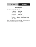
Страница 4: ...following materials have been shipped 1709070500 SATA Cable 1702150155 SATA Power Cable 9657666600 Jumper Cap Heat Spreader by model request DVD ROM for manual in PDF format and drivers EPIC KB07 If a...

Страница 5: ...2 5 List of Connectors 2 8 2 6 Setting Jumpers 2 10 2 7 LVDS1 Backlight Voltage Selection JP1 2 11 2 8 LVDS1 Backlight Control Selection JP2 2 11 2 9 LVDS1 VCC Selection JP3 2 11 2 10 LVDS2 Backlight...

Страница 6: ...P0 Connector CN7 2 18 2 28 1st Backlight Connector CN10 2 19 2 29 1st LVDS Connector CN11 2 19 2 30 2nd Backlight Connector CN13 2 21 2 31 2nd LVDS Connector CN14 2 21 2 32 3G SIM Connector CN15 2 23...

Страница 7: ...2 51 4 Pin Power IN Connector CN35 2 39 2 52 2 Pin Power IN Connector CN36 2 39 2 53 1st MINI Card Slot PCIE1A1 2 40 2 54 2nd MINI Card Slot PCIE1A2 2 42 2 55 USB2 0 Connector USB1 2 45 2 56 USB2 0 Co...

Страница 8: ...5 Appendix B I O Information B 1 I O Address Map B 2 B 2 Memory Address Map B 4 B 3 IRQ Mapping Chart B 5 B 4 DMA Channel Assignments B 8 Appendix C Mating Connector C 1 List of Mating Connectors and...

Страница 9: ...EPIC Board E P I C K B 0 7 Chapter 1 General Information 1 1 General Information Chapter 1...

Страница 10: ...p to 8GB Moreover EPIC KB07 deploys Realtek 8111E Ethernet chip to feature two RJ 45 ports onboard to display the transcendent performance of network connections The display chipset of EPIC KB07 suppo...

Страница 11: ...ion supports dual displays and VGA DP0 default setting VGA DP1 VGA LVDS1 18 bit Single Channel or LVDS2 DP0 Rear I O or HDMI VGA DP0 Rear I O or HDMI LVDS2 24 bit Dual Channel LVDS1 18 bit Single Chan...

Страница 12: ...Fintek 81866D Ethernet 10 100 1000Base TX Realtek 8111E RJ 45 x 2 BIOS AMI Plug Play BIOS Wake On LAN Yes Watchdog Timer Generates a time out system reset H W Status Monitoring Monitoring system temp...

Страница 13: ...displays Chipset AMD Embedded G series SoC integrated Resolutions Up to 2048x1536 75 Hz for CRT 1920x1200 85Hz for LCD 1920x1200 60Hz for DisplayPort LCD Interface VGA DP1 VGA LVDS1 18 bit Single CH...

Страница 14: ...RS 232 x 4 RS 232 422 485 x 2 Parallel Port SPP EPP ECP Mode USB USB2 0 x 5 USB3 0 x 2 PS 2 Port Keyboard x 1 Mouse x 1 Digital I O Supports 16 bit programmable Colay with LPT Port default and select...

Страница 15: ...EPIC Board E P I C K B 0 7 Chapter 2 Quick Installation Guide 2 1 Quick Installation Guide Chapter 2...

Страница 16: ...le the power is on because a sudden rush of power can damage sensitive electronic components Always ground yourself to remove any static charge before touching the board Modern electronic devices are...

Страница 17: ...EPIC Board E P I C K B 0 7 Chapter 2 Quick Installation Guide 2 3 2 2 Location of Connectors and Jumpers Component Side Component Side...

Страница 18: ...EPIC Board E P I C K B 0 7 Chapter 2 Quick Installation Guide 2 4 2 3 Mechanical Drawing Component Side Component Side...

Страница 19: ...EPIC Board E P I C K B 0 7 Chapter 2 Quick Installation Guide 2 5 With Heat Spreader b b c G G G G G G G G 3 0 e e Solder Side e Solder Side 6 3 2 6 3 2...

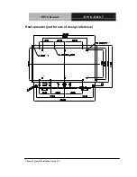
Страница 20: ...EPIC Board E P I C K B 0 7 Chapter 2 Quick Installation Guide 2 6 Heat spreader just for one of design reference 3 0 b b b b b b c c G G G G 3 0 e e e e e e...

Страница 21: ...unction JP1 LVDS1 Backlight Voltage Selection JP2 LVDS1 Backlight Control Selection JP3 LVDS1 VCC Selection JP4 LVDS2 Backlight Voltage Selection JP5 LVDS2 Backlight Control Selection JP6 LVDS2 VCC Se...

Страница 22: ...se Tx Ethernet LAN1 Connector CN6 1000 Base Tx Ethernet LAN2 Connector CN7 DP0 Connector CN9 Clear CMOS CN10 1 st Backlight Connector CN11 1 st LVDS Connector CN12 DP1 Connector CN13 2 nd Backlight Co...

Страница 23: ...CN30 COM5 RS 232 Serial Port Connector CN31 COM6 RS 232 Serial Port Connector CN32 VGA Connector CN33 RTC Battery Connector CN34 Front Panel Connector CN35 4 Pin Power In Connector CN36 2 Pin Power in...

Страница 24: ...hem To close a jumper you connect the pins with the clip To open a jumper you remove the clip Sometimes a jumper will have three pins labeled 1 2 and 3 In this case you would connect either pins 1 and...

Страница 25: ...LVDS1 Backlight Voltage Selection JP1 12V 5V JP1 Function 1 2 12V 2 3 5V Default 2 8 LVDS1 Backlight Control Selection JP2 Voltage Mode PWM Mode JP2 Function 1 2 Voltage Mode 2 3 PWM Mode Default 2 9...

Страница 26: ...Voltage Selection JP4 12V 5V JP4 Function 1 2 12V 2 3 5V Default 2 11 LVDS2 Backlight Control Selection JP5 Voltage Mode PWM Mode JP5 Function 1 2 Voltage Mode 2 3 PWM Mode Default 2 12 LVDS2 VCC Sele...

Страница 27: ...rt AT Default OPEN ATX 2 14 LPT_DIO Selection JP9 LPT DIO JP9 Function 1 2 short DIO OPEN LPT Default 2 15 COM2 Ring_12V_5V Selection JP10 12V RI2 5V JP10 Function 1 2 12V 3 4 RI2 Default 5 6 5V 2 16...

Страница 28: ...creen Selection JP12 4 8 Wires 5 Wires JP12 Function 1 2 short 4 8 Wires Default OPEN 5 Wires 2 18 COM1 Slew Selection JP13 250kbps 1M 10Mbps JP13 Function 1 2 Short 1Mbps 10Mbps Default OPEN 250kbps...

Страница 29: ...ction CN9 1 2 3 1 2 3 NORMAL CLEAR CMOS CN9 Function 1 2 Protected Default 2 3 Clear 2 21 mSATA PCIe Selection CN37 mSATA PCIe CN37 Function 1 2 Short PCIe OPEN mSATA Default 2 22 Display setting Sele...

Страница 30: ...4 24Bit OFF OFF 2 23 Fan Connector CN2 Pin Pin Name Signal Type Signal Level 1 GND GND 2 FAN_CTL OUT 3 FAN_TAC OUT 4 FAN_CTL_R OUT 2 24 SPI Flash Header CN3 Pin Pin Name Signal Type Signal Level 1 3V3...

Страница 31: ...D LED 8 Pin Pin Name Signal Type Signal Level 1 LAN1_MDI0P I O 2 LAN1_MDI0N I O 3 LAN1_MDI1P I O 4 LAN1_MDI1N I O 5 LAN1_MDI2P I O 6 LAN1_MDI2N I O 7 LAN1_MDI3P I O 8 LAN1_MDI3N I O 2 26 LAN2 Ethernet...

Страница 32: ...5 LAN2_MDI2P I O 6 LAN2_MDI2N I O 7 LAN2_MDI3P I O 8 LAN2_MDI3N I O 2 27 DP0 Connector CN7 Pin Pin Name Signal Type Signal Level 1 Lane0 P I O 2 GND GND 3 Lane0 N I O 4 Lane1 P I O 5 GND GND 6 Lane1 N...

Страница 33: ...GND 15 AUX CH P I O 16 GND GND 17 AUX CH N I O 18 Hot Plug 19 Return PWR GND GND 20 DP_PWR PWR 3 3V 2 28 1st Backlight Connector CN10 Pin Pin Name Signal Type Signal Level 1 INV_1ND_PWR PWR 5V OR 12V...

Страница 34: ...CTL OUT 3 VLCD_1ND PWR 3 3V OR 5V 4 GND GND 5 LVD1_A_CLKN OUT 6 LVD1_A_CLKP OUT 7 VLCD_1ND PWR 3 3V OR 5V 8 GND GND 9 LVD1_A_TXN2 I O 10 LVD1_A_TXP2 I O 11 LVD1_A_TXN1 I O 12 LVD1_A_TXP1 I O 13 LVD1_A...

Страница 35: ...4 NC NC 25 NC NC 26 NC NC 27 VLCD_1ND PWR 3 3V OR 5V 28 GND GND 29 NC NC 30 NC NC 2 30 2 nd Backlight Connector CN13 Pin Pin Name Signal Type Signal Level 1 INV_2ND_PWR PWR 5V OR 12V 2 LVD2_BKLCTL OUT...

Страница 36: ...V 4 GND GND 5 LVDS_A_CLKN I O 6 LVDS_A_CLKP I O 7 VLCD_2ND PWR 3 3V OR 5V 8 GND GND 9 LVDS_A_TX 0 I O 10 LVDS_A_TX0 I O 11 LVDS_A_TX 1 I O 12 LVDS_A_TX1 I O 13 LVDS_A_TX 2 I O 14 LVDS_A_TX2 I O 15 LVD...

Страница 37: ...DS_B_TX 3 I O 26 LVDS_B_TX3 I O 27 VLCD_2ND PWR 3 3V OR 5V 28 GND GND 29 LVDS_B_CLKN I O 30 LVDS_B_CLKP I O 2 32 3G SIM Connector CN15 Pin Pin Name Signal Type Signal Level 1 UIM_PWR PWR 3 3V 2 UIM_RS...

Страница 38: ...O 7 GND GND 8 USB3_TX0_CON_N I O 9 USB3_TX0_CON_P I O 10 V5A_USB_0 PWR 5V 11 USBD9 I O 12 USBD9 I O 13 GND GND 14 USB3_RX1_CON_N I O 15 USB3_RX1_CON_P I O 16 GND GND 17 USB3_TX1_CON_N I O 18 USB3_TX1_...

Страница 39: ...type Signal Level 1 GND GND 2 SATA_TXP0_C I O 3 SATA_TXN0_C I O 4 GND GND 5 SATA_RXN0_C I O 6 SATA_RXP0_C I O 7 GND GND 2 35 SATA CONNCETOR CN18 Pin Pin Name Signal Type Signal Level 1 GND GND 2 SATA...

Страница 40: ...ide 2 26 2 36 SATA Power Connector CN19 Pin Pin Name Signal Type Signal Level 1 5V PWR 5V 2 GND GND GND 2 37 RS 232 Serial Port Dual Connector CN20 COM1 RS 232 Pin Pin Name Signal Type Signal Level 1...

Страница 41: ...9 RI1_5V_12V IN PWR COM2 RS 232 Pin Pin Name Signal Type Signal Level 1 DCD2 IN 2 RX2 IN 3 TX2 OUT 4 DTR2 OUT 5 GND GND 6 DSR2 IN 7 RTS2 OUT 8 CTS2 IN 9 RI2_5V_12V IN PWR COM1 2 RS 422 Pin Pin Name Si...

Страница 42: ...n Guide 2 28 8 NC 9 NC 5V 12V PWR 5V 12V COM1 2 RS 485 Pin Pin Name Signal Type Signal Level 1 485D I O 2 485D I O 3 NC 4 NC 5 NC 6 NC 7 NC 8 NC 9 NC 5V 12V PWR 5V 12V 2 38 RS 232 Serial Port Connecto...

Страница 43: ...nstallation Guide 2 29 2 DSR3 IN 3 RX3 IN 4 RTS3 OUT 5 TX3 OUT 6 CTS3 IN 7 DTR3 OUT 8 RI3 IN 9 GND GND 2 39 LPT_DIO Connector CN22 LPT Mode Pin Pin Name Signal Type Signal Level 1 STOBE I O 2 AFD I O...

Страница 44: ...SLIN I O 9 PPD3 I O 10 GND GND 11 PPD4 I O 12 GND GND 13 PPD5 I O 14 GND GND 15 PPD6 I O 16 GND GND 17 PPD7 I O 18 GND GND 19 ACK I O 20 GND GND 21 BUSY I O 22 GND GND 23 PE I O 24 GND GND 25 SLCT I O...

Страница 45: ...0 I O 4 GPIO13 I O 5 GPIO1 I O 6 GPIO12 I O 7 GPIO2 I O 8 GPIO11 I O 9 GPIO3 I O 10 GND GND 11 GPIO4 I O 12 GND GND 13 GPIO5 I O 14 GND GND 15 GPIO6 I O 16 GND GND 17 GPIO7 I O 18 GND GND 19 GPIO10 I...

Страница 46: ...apter 2 Quick Installation Guide 2 32 2 40 RS 232 Serial Port Connector CN23 Pin Pin Name Signal Type Signal Level 1 DCD4 IN 2 DSR4 IN 3 RX4 IN 4 RTS4 OUT 5 TX4 OUT 6 CTS4 IN 7 DTR4 OUT 8 RI4 IN 9 GND...

Страница 47: ...Name Signal Type Signal Level 1 LAD0 I O 2 LAD1 I O 3 LAD2 I O 4 LAD3 I O 5 3 3V PWR 3 3V 6 LFRAME IN 7 BUF_PLTRST IN 8 GND GND 9 LPC_CLK1 OUT 10 LDRQ0 OUT 11 NC NC 12 SERIRQ I O 2 42 Touch Screen Co...

Страница 48: ...nstallation Guide 2 34 4 X IN 5 X IN 6 SENSE IN 7 Y IN 8 X IN 9 X IN 2 43 Audio Connector CN26 Pin Pin Name Signal Type Signal Level 1 MIC_L IN 2 MIC_R IN 3 AUD_GND GND 4 LIN_L IN 5 LIN_R IN 6 AUD_GND...

Страница 49: ...de 2 35 10 VDD_AUD PWR 5VSB 2 44 AMP R Channel Connector CN27 Pin Pin Name Signal Type Signal Level 1 SKR_R OUT 2 SKR_R OUT 2 45 AMP L Channel Connector CN28 Pin Pin Name Signal Type Signal Level 1 SK...

Страница 50: ...2 36 Pin Pin Name Signal Type Signal Level 1 DCD5 IN 2 DSR5 IN 3 RX5 IN 4 RTS5 OUT 5 TX5 OUT 6 CTS5 IN 7 DTR5 OUT 8 RI5 IN 9 GND GND 2 47 RS 232 Serial Port Connector CN31 Pin Pin Name Signal Type Si...

Страница 51: ...DTR6 OUT 8 RI6 IN 9 GND GND 2 48 VGA CONNECTOR CN32 Pin Pin Name Signal Type Signal Level 1 RED I O 2 GREEN I O 3 BLUE I O 4 NC 5 GND GND 6 GND GND 7 GND GND 8 GND GND 9 5V PWR 5V 10 CRT_PLUG IN 11 NC...

Страница 52: ...2 38 18 NC 19 NC 2 49 RTC Battery Connector CN33 Pin Pin Name Signal Type Signal Level 1 RTCBAT PWR 3 3V 2 GND GND 2 50 Front Panel Connector CN34 Pin Pin Name Signal Type Signal Level 1 PWRSIN IN 2...

Страница 53: ...7 3 3V PWR 3 3V 8 GND GND 9 HWRST IN 10 GND GND 2 51 4 Pin Power IN Connector CN35 Pin Pin Name Signal Type Signal Level 1 GND GND 2 GND GND 3 VIN PWR 12V 4 VIN PWR 12V 2 52 2 Pin Power IN Connector...

Страница 54: ...rd Slot PCIE1A1 Pin Pin Name Signal Type Signal Level 1 PCIE_WAKE OUT 2 3 3V_A_MC1 PWR 3 3V 3 Reserved 4 GND GND 5 Reserved 6 1 5V PWR 1 5V 7 PEGB_CLKRQ OUT 8 Reserved 9 GND GND 10 Reserved 11 mSATA_P...

Страница 55: ...20 W_DISABLE IN 21 XSD OUT 22 BUF_PLTRST IN 23 PERn0_RX I O 24 3 3V_A_MC1 PWR 3 3V 25 PERp0_RX DIFF 26 GND GND 27 GND GND 28 1 5V PWR 1 5V 29 GND GND 30 SCLK1 I O 31 PETn0_TX I O 32 SDATA1 I O 33 PETp...

Страница 56: ...V 42 Reserved 43 NC 44 Reserved 45 Reserved I O 46 Reserved 47 Reserved I O 48 1 5V PWR 1 5V 49 Reserved I O 50 GND GND 51 Reserved I O 52 3 3V_A_MC1 PWR 3 3V 2 54 2 nd MINI Card Slot PCIE1A2 Pin Pin...

Страница 57: ...WR 9 GND GND 10 UIM_DAT 11 MiniCard2_CLKN I O 12 UIM_CLK 13 MiniCard2_CLKP I O 14 UIM_RST 15 GND GND 16 UIM_VPP OUT 3 3V 17 Reserved 18 GND GND 19 Reserved 20 W_DISABLE IN 21 GND GND 22 BUF_PLT_RST IN...

Страница 58: ...3_N I O 32 SDATA1 I O 33 PCIE_MiniCard2_TX3_P I O 34 GND GND 35 GND GND 36 USB5N I O 37 GND GND 38 USB5P I O 39 3 3V_A_MC2 PWR 3 3V 40 GND GND 41 3 3V_A_MC2 PWR 3 3V 42 Reserved 43 GND GND 44 Reserved...

Страница 59: ...2 45 2 55 USB2 0 Connector USB1 Pin Pin Name Signal Type Signal Level 1 V5A_USB_1 PWR 5V 2 USBD0 I O 3 USBD0 I O 4 GND GND 5 GND GND 2 56 USB2 0 Connector USB2 Pin Pin Name Signal Type Signal Level 1...

Страница 60: ...e 2 46 2 57 USB2 0 Connector USB3 Pin Pin Name Signal Type Signal Level 1 V5A_USB_2 PWR 5V 2 USBD2 I O 3 USBD2 I O 4 GND GND 5 GND GND 2 58 USB Connector USB4 Pin Pin Name Signal Type Signal Level 1 V...

Страница 61: ...59 USB Connector USB5 Pin Pin Name Signal Type Signal Level 1 V5A_USB_3 PWR 5V 2 USBD7 I O 3 USBD7 I O 4 GND GND 5 GND GND 2 60 PS2 Keyboard and Mouse Connector KB1 Pin Pin Name Signal Type Signal Lev...

Страница 62: ...onnector HDMI1 Pin Pin Name Signal Type Signal Level 1 TMDS_DAT2 DIFF 2 GND GND 3 TMDS_DAT2 DIFF 4 TMDS_DAT1 DIFF 5 GND GND 6 TMDS_DAT1 DIFF 7 TMDS_DAT0 DIFF 8 GND GND 9 TMDS_DAT0 DIFF 10 TMDS_CLK DIF...

Страница 63: ...EPIC Board E P I C K B 0 7 Chapter 2 Quick Installation Guide 2 49 18 5V PWR 5V 19 HPLG_DETECT...

Страница 64: ...Board E P I C K B 0 7 Chapter 2 Quick Installation Guide 2 50 Below Table for China RoHS Requirements AAEON Main Board Daughter Board Backplane Pb Hg Cd Cr VI PBB PBDE O SJ T 11363 2006 X SJ T 11363...

Страница 65: ...EPIC Board E P I C K B 0 7 Chapter 3 AMI BIOS Setup 3 1 AMI BIOS Setup Chapter 3...

Страница 66: ...urrent system configuration against the values stored in the CMOS memory If they do not match the program outputs an error message You will then need to run the BIOS setup program to set the configura...

Страница 67: ...that it retains the Setup information when the power is turned off Entering Setup Power on the computer and press Del or F2 immediately This will allow you to enter Setup Main Set the date use tab to...

Страница 68: ...er 3 AMI BIOS Setup 3 4 Setup Menu Setup submenu Main Options summary default setting System Date Day MM DD YYYY Change the month year and century The Day is changed automatically System Time HH MM SS...

Страница 69: ...up submenu Advanced Options summary default setting ACPI Settings System ACPI Parameters CPU Configuration CPU Configuration Parameters IDE Configuration SATA Device Options Settings USB Configuration...

Страница 70: ...K B 0 7 Chapter 3 AMI BIOS Setup 3 6 System Super IO Chip Parameters F81866 H W Monitor Monitor hardware status Dynamic Digital IO Dynamic Digital IO settings Power Management ATX AT Power Failure Wak...

Страница 71: ...I C K B 0 7 Chapter 3 AMI BIOS Setup 3 7 ACPI Settings Options summary default setting ACPI Sleep State S3 Suspend to RAM Select the highest ACPI sleep state the system will enter when the SUSPEND but...

Страница 72: ...EPIC Board E P I C K B 0 7 Chapter 3 AMI BIOS Setup 3 8 CPU Configuration...

Страница 73: ...EPIC Board E P I C K B 0 7 Chapter 3 AMI BIOS Setup 3 9 IDE Configuration Options summary default setting OnChip SATA Type ACHI Legacy IDE Configure SATA controller operating as Legacy IDE AHCI mode...

Страница 74: ...SB Configuration Options summary default setting Legacy USB Support Enabled Disabled Auto Enables Legacy USB Support AUTO option disables legacy support if no USB devices are connected DISABLE option...

Страница 75: ...K B 0 7 Chapter 3 AMI BIOS Setup 3 11 F81866 Super IO Configuration Options summary default setting Serial Port x Configuration Set Parameters of Serial Port x Parallel Port Configuration Set Paramete...

Страница 76: ...Serial Port 1 2 Configuration Options summary default setting Serial Port Disabled Enabled En Disable specified serial port Change Settings Auto IO 3F8h IRQ 4 IO 3F8h IRQ 3 4 IO 2F8h IRQ 3 4 Select an...

Страница 77: ...EPIC Board E P I C K B 0 7 Chapter 3 AMI BIOS Setup 3 13 RS422 RS485 Select an optimal setting for Super IO device...

Страница 78: ...up 3 14 Serial Port 3 4 5 6 Configuration Options summary default setting Serial Port Disabled Enabled En Disable specified serial port Change Settings Auto IO 3F8h IRQ 4 IO 3F8h IRQ 3 4 IO 2F8h IRQ 3...

Страница 79: ...ter 3 AMI BIOS Setup 3 15 Parallel Port Configuration Options summary default setting Parallel Port Disabled Enabled En Disable Parallel port Change Settings Auto IO 378h IRQ 5 IO 378h IRQ 5 6 7 10 11...

Страница 80: ...16 IO 3BCh IRQ 5 6 7 10 11 12 Select an optimal setting for Super IO device Device Mode STD Printer Mode SPP Mode EPP 1 9 and SPP Mode EPP 1 7 and SPP Mode ECP Mode ECP and EPP 1 9 Mode ECP and EPP 1...

Страница 81: ...Chapter 3 AMI BIOS Setup 3 17 F81866 H W Monitor Options summary default setting Smart Fan Function Disabled Enabled En Disable specified Smart Fan Function Smart Fan Mode Configuration Select an opt...

Страница 82: ...an1 Smart Fan Control Manual Duty Mode Auto Duty Cycle Mode Smart Fan Mode Select Manual Duty Mode Manual mode fan control from 1 100 Temperature x Fan speed will follow different temperature by diffe...

Страница 83: ...0 7 Chapter 3 AMI BIOS Setup 3 19 Dynamic Digital IO Options summary default setting GPIx GPOx Direction Input Output Select GPIx GPOx I O direction Output Level Hi Low Select the output level when s...

Страница 84: ...C K B 0 7 Chapter 3 AMI BIOS Setup 3 20 Power Management Configuration Options summary default setting Power Mode AT Type ATX Type Select power supply mode Resume from PCIE Enabled Disabled En Dis PC...

Страница 85: ...EPIC Board E P I C K B 0 7 Chapter 3 AMI BIOS Setup 3 21 Setup submenu Chipset Options summary default setting North Bridge North Bridge Parameters South Bridge South Bridge Parameters...

Страница 86: ...EPIC Board E P I C K B 0 7 Chapter 3 AMI BIOS Setup 3 22 North Bridge Options summary default setting GFX Configuration Configure Graphics Settings...

Страница 87: ...I BIOS Setup 3 23 GFX Configuration Options summary default setting DP0 Output Mode DP HDMI LVDS Disabled DP0 Output Mode EDID Panel Support Enabled Disabled Chipset will load panel EDID DP0 mode as L...

Страница 88: ...ess of LVDS LVDS1 Backlight Type Normal Inverted Select Backlight Control Type DP1 Output Mode DP LVDS HDMI Disabled DP01 Output Mode LVDS2 Enabled Disabled LVDS CH7511 Enabled Disabled DP1 mode as DP...

Страница 89: ...3 25 1366x768 24bit 60Hz 1440x900 48bit 60Hz 1600x1200 48bit 60Hz 1920x1080 48bit 60Hz 1920x1200 48bit 60Hz LVDS2 resolution LVDS2 Backlight Level Select Backlight brightness of LVDS LVDS2 Backlight...

Страница 90: ...EPIC Board E P I C K B 0 7 Chapter 3 AMI BIOS Setup 3 26 South Bridge Options summary default setting HD Audio Azalia Device Auto Disabled Enabled Options for SB HD Azalia...

Страница 91: ...3 27 Setup submenu Boot Options summary default setting Quiet Boot Disabled Enabled En Disable showing boot logo Launch PXE OpROM Disabled Enabled En Disable PXE boot for RTL8111E LAN Boot Option x S...

Страница 92: ...C Board E P I C K B 0 7 Chapter 3 AMI BIOS Setup 3 28 Set the order of the legacy devices in this group Setup submenu Security Options summary default setting Administrator Password User Password Not...

Страница 93: ...s item a dialog box appears which lets you enter a password You can enter no more than six letters or numbers Press Enter after you have typed in the password A second dialog box asks you to retype th...

Страница 94: ...setting Save Changes and Reset Reset the system after saving the changes Discard Changes and Reset Reset system setup without saving any changes Restore Defaults Restore Load Default values for all th...

Страница 95: ...EPIC Board E P I C K B 0 7 Chapter 3 AMI BIOS Setup 3 31 Restore the User Defaults to all the setup options...

Страница 96: ...EPIC Board E P I C K B 0 7 Chapter 4 Driver Installation 4 1 Driver Installation Chapter 4...

Страница 97: ...nd utilities that meet your needs Follow the sequence below to install the drivers Step 1 Install Chipset Display Driver Step 2 Install LAN Driver Step 3 Install Audio Driver Step 4 Install ACPI Drive...

Страница 98: ...instructions that the window shows 4 The system will help you install the driver automatically Step 2 Install LAN Driver 1 Click on the STEP2 LAN folder and select the OS folder your system is 2 Doub...

Страница 99: ...tion is complete reboot the computer To uninstall 1 Run Device Manager select device item which Device Id equal ASD0001 2 Right click the device item and then chose Uninstall and then chose delete dri...

Страница 100: ...Step 5 Install UART Driver For Windows XP 1 Click on the STEP5 UART folder and select the folder of xp_x86 2 Double click on the Setup exe 3 Follow the instructions that the window shows 4 The system...

Страница 101: ...EPIC Board E P I C K B 0 7 Chapter 4 Driver Installation 4 6...

Страница 102: ...EPIC Board E P I C K B 0 7 Chapter 4 Driver Installation 4 7...

Страница 103: ...EPIC Board E P I C K B 0 7 Chapter 4 Driver Installation 4 8 For Windows 8...

Страница 104: ...EPIC Board E P I C K B 0 7 Chapter 4 Driver Installation 4 9...

Страница 105: ...E P I C K B 0 7 Chapter 4 Driver Installation 4 10 Step 6 Install Touch Driver 1 Click on the STEP6 TOUCH folder and select the OS folder your system is 2 Double click on the Setup exe located in each...

Страница 106: ...EPIC Board E P I C K B 0 7 Chapter 4 Driver Installation 4 11 3 Follow the instructions that the window shows 4 The system will help you install the driver automatically...

Страница 107: ...EPIC Board E P I C K B 0 7 Appendix A Programming the Watchdog Timer A 1 Programming the Watchdog Timer Appendix A...

Страница 108: ...l watchdog timer program is also attached based on which you can develop customized program to fit your application Configuring Sequence Description After the hardware reset or power on reset the FINT...

Страница 109: ...e performed during Wait for Key state To ensure the initial state of the key check logic it is necessary to perform four write opera tions to the Special Address port 2EH Two different enter keys are...

Страница 110: ...EPIC Board E P I C K B 0 7 Appendix A Programming the Watchdog Timer A 4 Watch Dog Timer 1 2 3 Control Register Index F5h F6h FAh Default 00h...

Страница 111: ...out Set wdt timer aaeonWdtSetEnable BOOL bEnable Enable wdt aaeonSuperIOClose Void aaeonSuperIOOpen Config F81866 Entry key aaeonioWritePortByte F81866_INDEX 0x87 aaeonioWritePortByte F81866_INDEX 0x8...

Страница 112: ..._BASEADDR_REG_MSB 8 f81866ReadByte F81866_WDT_BASEADDR_REG_LSB WDT_STATUS f81866ReadByte F81866_WDT_CONTROL_REG f81866WriteByte F81866_WDT_CONTROL_REG WDT_STATUS 0x20 WDT_STATUS f81866ReadByte F81866_...

Страница 113: ...EPIC Board E P I C K B 0 7 Appendix A Programming the Watchdog Timer A 7 Void aaeonSuperIOClose aaeonioWritePortByte F81866_INDEX 0xaa...

Страница 114: ...EPIC Board E P I C K B 0 7 Appendix B I O Information B 1 I O Information Appendix B...

Страница 115: ...EPIC Board E P I C K B 0 7 Appendix B I O Information B 2 B 1 I O Address Map...

Страница 116: ...EPIC Board E P I C K B 0 7 Appendix B I O Information B 3...

Страница 117: ...EPIC Board E P I C K B 0 7 Appendix B I O Information B 4 B 2 Memory Address Map...

Страница 118: ...EPIC Board E P I C K B 0 7 Appendix B I O Information B 5 B 3 IRQ Mapping Chart...

Страница 119: ...EPIC Board E P I C K B 0 7 Appendix B I O Information B 6...

Страница 120: ...EPIC Board E P I C K B 0 7 Appendix B I O Information B 7...

Страница 121: ...EPIC Board E P I C K B 0 7 Appendix B I O Information B 8 B 4 DMA Channel Assignments...

Страница 122: ...EPIC Board E P I C K B 0 7 Appendix C Mating Connector C 1 Mating Connector Appendix C...

Страница 123: ...ctor E call 0109 02 522 300 CN13 2nd Backlight Connector CATCH H732 05 CN14 2nd LVDS Connector E call 0109 02 522 300 CN17 SATA Connector PINREX 1709070500 CN18 SATA Connector PINREX 1709070500 CN19 S...

Страница 124: ...OM6 RS 232 Serial Port Connector PINREX 712 75 09W001 1701090150 CN33 RTC Battery Connector PINREX 712 75 02W001 CN34 Front Panel Connector PINREX 712 75 10W001 USB1 USB2 0 Connector PINREX 712 75 05W...

Страница 125: ...EPIC Board E P I C K B 0 7 Appendix D Electrical Specifications for I O Ports D 1 Electrical Specifications for I O Ports Appendix D...

Страница 126: ...nnector CN13 VDD 5V 1A or 12V 1A 5V Output for SATA HDD CN19 5V 5V 1A Audio I O Port CN26 5V 5V 0 5A 2Pin PWRIN Optional CN36 VIN 12V 3A ATX 4Pin PWRIN CN35 VIN 12V 3A FAN CN2 12V 12V 0 5A mSATA Slot...

Страница 127: ...EPIC Board E P I C K B 0 7 Appendix D Electrical Specifications for I O Ports D 3 DP0 CN7 3 3V 3 3V 0 5A DP1 CN12 3 3V 3 3V 0 5A HDMI HDMI1 5V 5V 1A...

Страница 128: ...EPIC Board E P I C K B 0 7 Appendix E DIO E 1 DIO Appendix E...

Страница 129: ...EPIC Board E P I C K B 0 7 Appendix E DIO E 2 E 1 DIO The related register for configuring DIO is list as follows...

Страница 130: ...EPIC Board E P I C K B 0 7 Appendix E DIO E 3...

Страница 131: ...EPIC Board E P I C K B 0 7 Appendix E DIO E 4...

Страница 132: ...2E 0x87 Outportb 0x2E 0x07 set LDN Outportb 0x2F 0x06 Outportb 0x2E 0x88 GPIO set 8 register Outportb 0x2F 0x00 Set GPIO8x DIO 0 7 as input mode Outportb 0x2E 0x80 GPIO set 7 register Outportb 0x2F 0x...

Отзывы: