


E P I C B o a r d
E P I C - H D 0 7
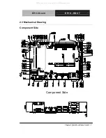
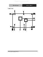
Chapter 1 General Information
1- 5
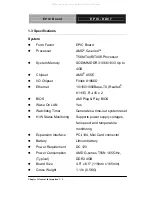
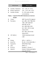
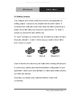
Operation
Temperature
32
°
F ~ 140
°
F (0
°
C ~ 60
°
C)
Storage
Temperature
-40
°
F ~ 176
°
F (-40
°
C ~ 80
°
C)
Operation Humidity
0% ~ 90% relative humidity,
non-condensing
Display: Supports CRT/LCD/DVI simultaneous/ dual view
displays
Chipset
AMD
®
G-series CPU integrated
Resolutions
Up to 2560 x 1600 T56N(18W)
1920 x 1200 T44R/T40R
(9W/5.5W) for CRT;
Up to 1920x1200 for DVI;
Up to 1400 x 1050 for single
channel LVDS;
Up to 1920 x 1200 for dual
channel LVDS
LCD
Interface
18/24-bit
dual/single
channel
LVDS
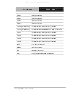
I/O
Storage
SATA x 1, mSATA x 1
Serial Port
RS-232 x 5, RS-232/422/485 x 1
Parallel
Port
SPP/EPP/ECP
Mode
USB
USB2.0
x
8
PS/2
Port
Keyboard x 1, Mouse x 1
Digital I/O
Supports 16-bit (programmable),
Colay with LPT Port
All manuals and user guides at all-guides.com


