


EPC-CV1 Series
2-16
7.
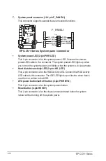
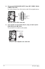
System panel connector (10-1 pin F_PANEL1)
This connector supports several chassis-mounted functions.
•
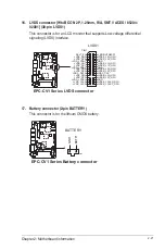
System power LED (2-pin PWR LED)
This 2-pin connector is for the system power LED. Connect the chassis
power LED cable to this connector. The system power LED lights up when
you turn on the system power, and blinks when the system is in sleep mode.
•
Hard disk drive activity LED (2-pin +HD_LED)
This 2-pin connector is for the HDD Activity LED. Connect the HDD Activity
LED cable to this connector. The IDE LED lights up or flashes when data is
read from or written to the HDD.
•
ATX power button/soft-off button (2-pin PWR BTN)
This 2-pin connector is for the system power button.
•
Reset button (2-pin RESET)
This 2-pin connector is for the chassis-mounted reset button for system
reboot without turning off the system power.
EPC-CV1 Series System panel connector
PIN 1
PWR BTN
PLED+
PLED-
PANSWH#
GND
HD_LED-
GND
HWRST#
(NC)
F_PANEL1
PWR LED
+HD_LED
RESET


