background image

T o u c h   P a n e l   P C  

A H P - 1 1 5 4


Advanced -> IDE Configuration 


Options summary: 

Serial-ATA(SATA) 

Enabled 

Default 

Disable 


SATA Speed Support 

Gen1 


Gen2 

Default 

SATA ODD Port 

Port0 ODD 


Port1 ODD 


No ODD 

Default 

SATA Mode 

IDE 


AHCI 

Default 

Chapter 3 AMI BIOS Setup   

3-19 

Содержание AHP-1154

Страница 1: ...Touch Panel PC A H P 1 1 5 4 AHP 1154 Intel Celeron J1900 N2807 Processor 15 TFT LCD Touch Panel PC AHP 1154 Manual 1 st Ed April 16 2015...

Страница 2: ...manual is intended to be accurate and reliable However the original manufacturer assumes no responsibility for its use or for any infringements upon the rights of third parties that may result from i...

Страница 3: ...I is a trademark of American Megatrends Inc Intel and Celeron are trademarks of Intel Corporation Microsoft Windows is a registered trademark of Microsoft Corp IBM PC AT PS 2 and VGA are trademarks of...

Страница 4: ...sure that the following materials are enclosed AHP 1154 Touch Panel PC Phoenix Terminal Block Mounting brackets and screws DVD for manual in PDF format and drivers If any of these items should be mis...

Страница 5: ...Dropping it or letting it fall could cause damage 6 The openings on the device s enclosure are for dissipating heat DO NOT COVER THE OPENINGS 7 Watch out for high temperatures that may occur during s...

Страница 6: ...14 If any of the following situations arises please the contact our service personnel i Damaged power cord or plug ii Liquid intrusion to the device iii Exposure to moisture iv Device is not working...

Страница 7: ...vice must accept any interference received including interference that may cause undesired operation Caution There is a danger of explosion if the battery is incorrectly replaced Replace only with the...

Страница 8: ...Touch Panel PC A H P 1 1 5 4 China RoHS Requirements AAEON Panel PC Workstation Pb Hg Cd Cr VI PBB PBDE O SJ T 11363 2006 X SJ T 11363 2006 vii...

Страница 9: ...2 2 2 COM 1 4 D SUB 9 2 4 2 3 COM 2 3 D SUB 9 2 4 2 4 Hard Disk Drive Installation 2 6 Chapter 3 AMI BIOS Setup 3 1 System Test and Initialization 3 2 3 2 AMI BIOS Setup 3 3 Chapter 4 Driver Installa...

Страница 10: ...A H P 1 1 5 4 B 3 IRQ Mapping Chart B 6 Appendix C Mating Connector C 1 List of Mating Connectors and Cables C 2 Appendix D Electrical Specifications for I O Port D 1 Electrical Specifications for I...

Страница 11: ...Touch Panel PC A H P 1 1 5 4 Chapter 1 General Information 1 1 General Information Chapter 1...

Страница 12: ...ction computer In addition its fit anywhere design makes it very flexible and able to be used in many different kinds of installations It can be VESA 75 100 wall mounted For system integrators this si...

Страница 13: ...rmation 1 3 1 2 Features 15 450 nits XGA LED Backlight Intel Celeron J1900 2GHz N2807 1 58GHz Processor IP65 rated front plastic bezel back metal chassis Fanless Supports Windows 7 32 bit Windows Embe...

Страница 14: ...204 pin DDR3L 1333MHz SODIMM x 1 up to 8GB J1900 4GB N2807 2GB build in system RAM Integrated in Processor 10 100 1000Base TX RJ 45 x 2 USB 3 0 x 1 USB 2 0 x 3 RS 232 x 2 RS 232 422 485 x 2 COM2 COM3...

Страница 15: ...x 8 2 H x 17 9 D 505 mm x 210 mm x 455 mm Cutout Size for panel mount 394 x 297 5mm Net Weight 11 02lbs 5kg Gross Weight 14 99lbs 6 8kg Environmental Operating Temperature 13 9 F 122 F 10 C 50 C with...

Страница 16: ...lay Type 15 XGA TFT LCD Max Resolution 1024x768 Max Colors 16 8M 8 bit color Luminance cd m 2 450 nits Viewing Angle 160 o H 140 o V Backlight LED Backlight MTBF Hours 100 000 Touch Screen Type 5 wire...

Страница 17: ...Touch Panel PC A H P 1 1 5 4 Chapter 1 General Information 1 7 1 4 Product Overview...

Страница 18: ...Touch Panel PC A H P 1 1 5 4 Chapter 1 General Information 1 8...

Страница 19: ...Touch Panel PC A H P 1 1 5 4 Hardware Installation Chapter 2 Chapter 2 Quick Installation Guide 2 1...

Страница 20: ...trong mounting surface screws along with the mounting brackets Please take a look at the illustration below before starting to mount the panel Step 1 Prepare a 394mm x 297 5mm opening on the surface t...

Страница 21: ...rack inside each of the mount holes on the panel Insert each mount into the holes from the wide end of the track and push it towards the narrow end to secure Do this for all the mounts Step 5 Once all...

Страница 22: ...l Type Signal Level 1 DCD IN 2 RX IN 3 TX OUT 9V 4 DTR OUT 9V 5 GND GND 6 DSR IN 7 RTS OUT 9V 8 CTS IN 9 RI IN 2 3 COM 2 3 D SUB 9 RS 232 Pin Pin Name Signal Type Signal Level 1 DCD IN 2 RX IN 3 TX OU...

Страница 23: ...RS 422 Pin Pin Name Signal Type 1 RS422_TX OUT 2 RS422_TX OUT 3 RS422_RX IN 4 RS422_RX IN 5 GND GND 6 NC 7 NC 8 NC 9 NC 5V 12V PWR RS 485 Pin Pin Name Signal Type 1 RS485_D I O 2 RS485_D I O 3 NC IN 4...

Страница 24: ...cover Step 2 Remove the HDD bracket Step 3 Place the HDD onto the bracket Tighten the screws to secure Step 4 Connect the SATA cable to the HDD Step 5 Tighten the screws to secure the assembly to the...

Страница 25: ...Touch Panel PC A H P 1 1 5 4 AMI BIOS Setup Chapter 3 Chapter 3 AMI BIOS Setup 3 1...

Страница 26: ...against the values stored in the CMOS memory If they do not match the program outputs an error message You will then need to run the BIOS setup program to set the configuration information in memory...

Страница 27: ...n when the power is turned off Entering Setup Power on the computer and press Del or F2 immediately This will allow you to enter Setup Main Set the date use tab to switch between date elements Advance...

Страница 28: ...Touch Panel PC A H P 1 1 5 4 BIOS Setup Menu Setup submenu Main Press Delete to enter Setup Chapter 3 AMI BIOS Setup 3 4...

Страница 29: ...Touch Panel PC A H P 1 1 5 4 Setup submenu Advanced Chapter 3 AMI BIOS Setup 3 5...

Страница 30: ...efault Failsafe Default AT Type Select power supply mode Restore AC Power Loss Power Off Power On Last State Optimal Default Failsafe Default Select AC power state when power is re applied after a pow...

Страница 31: ...Disables System ability to Hibernate OS S4 Sleep State This option may be not effective with some OS Lock Legacy Resources Enable Disable Optimal Default Failsafe Default Enables or Disables Lock of...

Страница 32: ...Wake Settings Options summary Wake system with Fixed Time Enable Disable Optimal Default Failsafe Default Wake up hour 0 Wake up minute 0 Wake up second 0 Wake system with Dynamic Time Enable Disable...

Страница 33: ...Touch Panel PC A H P 1 1 5 4 Wake up minute increase 0 Select RTC wake mode Advanced Super IO Configuration Chapter 3 AMI BIOS Setup 3 9...

Страница 34: ...Touch Panel PC A H P 1 1 5 4 Advanced Super IO Configuration Serial Port 1 Configuration Chapter 3 AMI BIOS Setup 3 10...

Страница 35: ...Touch Panel PC A H P 1 1 5 4 Advanced Super IO Configuration Serial Port 2 Configuration Chapter 3 AMI BIOS Setup 3 11...

Страница 36: ...Touch Panel PC A H P 1 1 5 4 Advanced Super IO Configuration Serial Port 3 Configuration Chapter 3 AMI BIOS Setup 3 12...

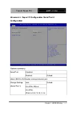
Страница 37: ...ation Serial Port 4 Configuration Options summary Serial Port Disabled Enabled Default Allows BIOS to En Disable correspond serial port Change Settings Serial Port 1 Auto Default IO 3F8h IRQ 4 IO 3F8h...

Страница 38: ...al Port resource Change Settings Serial Port 2 Auto Default IO 2F8h IRQ 3 IO 3F8h IRQ 3 4 5 6 7 9 10 11 12 IO 2F8h IRQ 3 4 5 6 7 9 10 11 12 IO 3E8h IRQ 3 4 5 6 7 9 10 11 12 IO 2E8h IRQ 3 4 5 6 7 9 10...

Страница 39: ...RQ 3 4 5 6 7 9 10 11 12 IO 2F0h IRQ 3 4 5 6 7 9 10 11 12 IO 2E0h IRQ 3 4 5 6 7 9 10 11 12 Working model RS232 Default RS422 RS485 Select Working model Change Settings Serial Port 4 Auto Default IO 2E8...

Страница 40: ...Touch Panel PC A H P 1 1 5 4 IO 2E8h IRQ 3 4 5 6 7 9 10 11 12 IO 2F0h IRQ 3 4 5 6 7 9 10 11 12 IO 2E0h IRQ 3 4 5 6 7 9 10 11 12 Advanced H W Monitor Chapter 3 AMI BIOS Setup 3 16...

Страница 41: ...onfiguration Options summary Intel Virtualization Technology Disabled Optimal Default Failsafe Default Enabled When enabled a VMM can utilize the additional hardware capabilities provided by Vander po...

Страница 42: ...Touch Panel PC A H P 1 1 5 4 Advanced CPU Configuration Socket 0 CPU Information Chapter 3 AMI BIOS Setup 3 18...

Страница 43: ...4 Advanced IDE Configuration Options summary Serial ATA SATA Enabled Default Disable SATA Speed Support Gen1 Gen2 Default SATA ODD Port Port0 ODD Port1 ODD No ODD Default SATA Mode IDE AHCI Default Ch...

Страница 44: ...as legacy IDE AHCI Configure SATA controllers to operate in AHCI mode Serial ATA Port0 1 Enabled Default Disable SATA Port0 1 HotPlug Enabled Disable Default Advanced CSM Configuration Options summar...

Страница 45: ...sable Boot option filter UEFI and Legacy Default Legacy only UEFI only Storage Video Do not launch Default UEFI only Legacy only Legacy first UEFI first Other PCI devices UEFI first Default Legacy onl...

Страница 46: ...dvanced Trusted Computing Options summary Security Device Support Enabled Default Disable TPM State Enabled Default Disable Pending Operation None Default Enable Take Ownership Disable Take Ownership...

Страница 47: ...imal Default Failsafe Default Disabled Auto Enables BIOS Support for Legacy USB Support When enabled USB can be functional in legacy environment like DOS AUTO option disables legacy support if no USB...

Страница 48: ...30MB will be emulated as Floppy and remaining as Floppy and remaining as hard drive Forced FDD option can be used to force a HDD formatted drive to boot as FDD Ex ZIP drive A Ad dv va an nc ce ed d T...

Страница 49: ...Touch Panel PC A H P 1 1 5 4 Chipset Chapter 3 AMI BIOS Setup 3 25...

Страница 50: ...Touch Panel PC A H P 1 1 5 4 Chipset Host Bridge Primary Boot Display VBIOS Default Default CRT DP HDMI Chapter 3 AMI BIOS Setup 3 26...

Страница 51: ...Touch Panel PC A H P 1 1 5 4 Chipset Host Bridge IGD LCD Control Chapter 3 AMI BIOS Setup 3 27...

Страница 52: ...Touch Panel PC A H P 1 1 5 4 Chipset South Bridge Chapter 3 AMI BIOS Setup 3 28...

Страница 53: ...Bridge USB Configuration Options summary USB OTG Support PCI mode Default Disable XHCI Mode Enabled Default Disabled Auto Smart Auto USB Per Port Control Enabled Default Disabled USB Port0 1 2 3 Enab...

Страница 54: ...dge PCI Express Configuration Options summary PCI Express Root Port 0 1 2 3 Disabled Enabled Optimal Default Failsafe Default Enabling Disabling PCI Express root ports Hot Plug Disabled Default Enable...

Страница 55: ...You can install a Supervisor password and if you install a supervisor password you can then install a user password A user password does not provide access to many of the features in the Setup utilit...

Страница 56: ...cond dialog box asks you to retype the password for confirmation Press Enter after you have retyped it correctly The password is required at boot time or when the user enters the Setup utility Removin...

Страница 57: ...H P 1 1 5 4 Boot Options summary Quiet Boot Disabled Enabled Default En Disable showing boot logo Launch i210 i211 PXE OpROM Disabled Default Enabled En Disable PXE boot for i210 i211 LAN Chapter 3 AM...

Страница 58: ...Touch Panel PC A H P 1 1 5 4 Exit Chapter 3 AMI BIOS Setup 3 34...

Страница 59: ...Touch Panel PC A H P 1 1 5 4 Driver Installation Chapter 4 Chapter 4 Driver Installation 4 1...

Страница 60: ...l the drivers Follow the sequence below to install the drivers Step 1 Install Chipset Driver Step 2 Install Graphics Driver Step 3 Install LAN Driver Step 4 Install PenMount Touch 6000 Driver Step 5 I...

Страница 61: ...the instructions 3 Drivers will be installed automatically Step 2 Install Graphics Driver 1 Open the Step 2 Graphics folder and select your OS 2 Open the Setup exe file in the folder 3 Follow the inst...

Страница 62: ...open the SetupTXE exe file 2 Follow the instructions 3 Drivers will be installed automatically Step 6 Install USB 3 0 Driver Windows 7 only 1 Open the Step 6 USB3 0 folder and open the Setup exe file...

Страница 63: ...Touch Panel PC A H P 1 1 5 4 Step 8 Install Serial Port Driver Optional Please follow the instructions in the Step8 Serial Port Driver Optional folder Chapter 4 Driver Installation 4 5...

Страница 64: ...Touch Panel PC A H P 1 1 5 4 Programming the Watchdog Timer Appendix A Appendix A Programming the Watchdog Timer A 1...

Страница 65: ...0x60 0x61 Table 2 Watchdog relative register table Register Offset BitNum Value Note Watchdog WDTRST Enable 0x00 7 1 Enable Disable time out output via WDTRST 0 Disable 1 Enable Pulse Width 0x05 0 1...

Страница 66: ...Output Signal Type 0x05 4 1 0 Level 1 Pulse Must set this bit to 1 Watchdog Timer Enable 0x05 5 1 0 Disable 1 Enable Timeout Status 0x05 6 1 1 timeout occurred Write a 1 to clear timeout status Timer...

Страница 67: ...80 Watchdog WDTRST Bit7 define WDTRstVal 0x80 Enabled WDTRST define TimerReg 0x05 Timer register define PSWidthBit 0x00 WDTRST Pulse width Bit0 1 define PSWidthVal 0x01 25ms for WDTRST pulse define Po...

Страница 68: ...ill enable the WDT counting WDTSetBit TimerReg PSWidthBit PSWidthVal Watchdog WDTRST Enable WDTSetBit DevReg WDTRstBit WDTRstVal VOID WDTClearTimeoutStatus WDTSetBit TimerReg StatusBit 1 VOID WDTWrite...

Страница 69: ...Touch Panel PC A H P 1 1 5 4 byte TmpValue TmpValue WDTReadByte Register TmpValue 1 Bit TmpValue Val Bit WDTWriteByte Register TmpValue Appendix A Programming the Watchdog Timer A 6...

Страница 70: ...Touch Panel PC A H P 1 1 5 4 I O Information Appendix B Appendix B I O Information B 1...

Страница 71: ...Touch Panel PC A H P 1 1 5 4 B 1 I O Address Map Appendix B I O Information B 2...

Страница 72: ...Touch Panel PC A H P 1 1 5 4 Appendix B I O Information B 3...

Страница 73: ...Touch Panel PC A H P 1 1 5 4 B 2 Memory Address Map Appendix B I O Information B 4...

Страница 74: ...Touch Panel PC A H P 1 1 5 4 Appendix B I O Information B 5...

Страница 75: ...Touch Panel PC A H P 1 1 5 4 B 3 IRQ Mapping Chart Appendix B I O Information B 6...

Страница 76: ...Touch Panel PC A H P 1 1 5 4 Appendix B I O Information B 7...

Страница 77: ...Touch Panel PC A H P 1 1 5 4 Appendix B I O Information B 8...

Страница 78: ...Touch Panel PC A H P 1 1 5 4 Appendix B I O Information B 9...

Страница 79: ...Touch Panel PC A H P 1 1 5 4 Appendix B I O Information B 10...

Страница 80: ...Touch Panel PC A H P 1 1 5 4 Appendix B I O Information B 11...

Страница 81: ...Touch Panel PC A H P 1 1 5 4 Mating Connector Appendix C Appendix C Mating Connector C 1...

Страница 82: ...nnector JST PHR 5 N A N A CN4 5Vout Connector JST PHR 2 2 Pins For SATA HDD Power 1702150155 CN5 External 5VSB Power Input and PS_ON JST XHP 3 ATX Cable 170220020B CN6 SATA Connector Molex 887505318 S...

Страница 83: ...0900 Serial Port Cable 1701090150 CN16 Digital IO Connector Molex 51110 1050 N A N A CN17 USB Port 3 Connector Molex 51021 0500 USB Cable 1700050207 CN18 USB Port 2 Connector Molex 51021 0500 USB Cab...

Страница 84: ...Touch Panel PC A H P 1 1 5 4 Electrical Specifications for I O Port Appendix D Appendix D Electrical Specifications for I O Port D 1...

Страница 85: ...0 375A LPC Port CN11 3 3V 3 3V 0 5A COM Port 2 CN12 5V 12V 5V 1A or 12V 1A COM Port 3 CN14 5V 12V 5V 1A or 12V 1A Digital IO Port CN16 5V 5V 1A USB 2 0 Ports 3 CN17 5VSB 5V 0 5A per channel USB 2 0 Po...

Отзывы: