


T o u c h P a n e l P C
A H P - 1 0 8 3
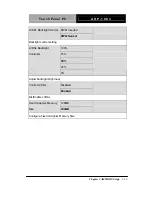
Intel IGD Configuration
Options summary: (
default setting
)
Disabled
Auto Disable IGD
Enabled
Auto disable IGD upon external GFX detected.
VBIOS Default
CRT
IGFX – Boot Type
1
st
LVDS
Select the Video Device which will be activated during POST
LCD Panel Type
800x600 18bit
Select 1
st
panel native resolution.
Chapter 3 AMI BIOS Setup
3-15
Содержание AHP-1083
Страница 9: ...Touch Panel PC A H P 1 0 8 3 Chapter 1 General Information 1 1 General Chapter 1 Information...
Страница 15: ...Touch Panel PC A H P 1 0 8 3 Chapter 2 Quick Installation Guide 2 1 Hardware Installation Chapter 2...
Страница 22: ...Touch Panel PC A H P 1 0 8 3 Chapter 2 Quick Installation Guide 2 8 Step 5 Connect the SATA cable to the HDD...
Страница 23: ...Touch Panel PC A H P 1 0 8 3 Chapter 3 AMI BIOS Setup 3 1 AMI Chapter 3 BIOS Setup...
Страница 48: ...Touch Panel PC A H P 1 0 8 3 Chapter 3 AMI BIOS Setup 3 26 Restore the User Defaults to all the setup options...
Страница 49: ...Touch Panel PC A H P 1 0 8 3 Chapter 4 Driver Installation 4 1 Driver Chapter 4 Installation...
Страница 53: ...Touch Panel PC A H P 1 0 8 3 Chapter 4 Driver Installation 4 5...


