A-TS
66
https://a-ts.cn/en/
Response delay refers to the time from the inverter receiving and
executing the command of the host to returning reply frame to the host.
For RTU mode, the actual response delay should be no less than 3.5
bytes’ transmitting time.
0: Slave
1: Master
Note: If master, usually used in multi-inverter interaction applications.
This parameter applies only to the slave, used for setting from the
receiving master given correction coefficient.
Slave given= PB.05 * ( Master given )
7.13 Professional parameters ( PC )
7.14 PLC parameters ( PD )
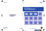
Simple PLC is a multi-speed generator, through which, the inverter can
change frequency and direction according to the running time. This
function is realized through PLC ( programmable logic controller )
before, now the inverter can do it by itself. See Figure 7-23.
Figure 7-23 Simple PLC Operation
In Figure 7-23, a1~a7, d1~d7 are the Acc and Dec time of the respective
stage; f1~f7 and T1~T7 will be defined in later parameters.
PB.04 Master-slave selection
Range: 0
~
1
【
0
】
PB.05 Ratio of slave inverter setting frequency
Range: 0
~
10.00
【
1.00
】
PC.00~ PC.14 Reserved
Reserved
f
1
f
2
f
3
f
4
f
5
f
6
f
7
T
1
T
2
T
3
T
4
T
5
T
6
T
7
a
1
a
2
a
3
d
3
a
4
d
5
a
5
a
6
d
7
d
7
Simple PLC operation
500m
s
Signal of completing one PLC stage
Signal of completing one PLC cycle