


32
DMA8825 / DMA8813 / DMA8425 / DMA8413
Español
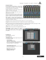
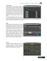
Eventos/Events
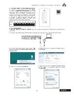
En el menú Eventos usted será capaz de establecer
una serie de eventos que se produzcan en un momento
determinado del día. Los eventos pueden ir desde
simplemente encender y apagar el dispositivo, o para
la activación de los archivos de audio en un momento
determinado�
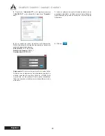
Hora Actual & Fecha Actual / Current Time & Current
Date:
Aquí los usuarios pueden establecer la fecha y la
hora actual. Haga clic en el botón Guardar para configurar
estos ajustes. La fecha y la hora se mantienen dentro del
amplificador DMA. Un suministro de energía está siempre
proporcionando a ese dispositivo, que el DMA sea activo
o en modo de espera�
Time Format/Formato de Hora:
selecciona el formato de
hora AM / PM o en 24 horas de tiempo�
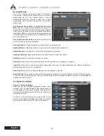
Schedule/Horario:
Todos los eventos ya establecidos se mostrarán aquí.
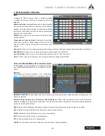
Number/Número:
Asigne un número al evento que está configurando actualmente.
Subject/Asunto:
Proporcione un nombre o una descripción a su evento.
Location/Ubicación:
Describa la ubicación del lugar donde se producirá el evento.
File/Fecha:
Ajuste la fecha para comenzar su evento.
Time/Hora:
Ajuste la hora del evento indicando cuando ese debe ocurrir, hasta en el segundo.
Type/Tipo:
Seleccione el tipo de evento que usted quiere configurar. Los tipos disponibles son: Cambio de potencia,
silenciamiento del canal, relay y tarjeta SD.
Action/Acción:
La acción se puede seleccionar entre encendido y standby.
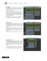
Period/Período:
En la sección periodo usted será capaz de establecer si quiere configurar el evento de forma que ese
ocurra una vez, de forma semanal, diaria, etc Usted también puede escoger los días de la semana para establecer
cuando este evento ocurra�
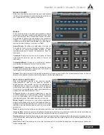
Configuración Global
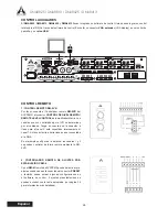
Analog In / Entrada Análoga
Cada una de las entradas analógicas pueden tener
aplicado +48 V de poder fantasma, ideal para micrófonos
de condensador. Este menú también permite que el
usuario ajuste de forma ligera la señal si los niveles son
demasiado excesivo�
Un filtro de paso alto también se puede añadir a cada
una de las entradas analógicas para ayudar a eliminar
vibraciones de escenario y otros ruidos no deseados.
Содержание DMA8825
Страница 1: ...User s Manual Manual del Usuario Digital Matrix Amplifiers DMA8825 DMA88 1 3 DMA8425 DMA84 1 3...
Страница 22: ......
Страница 41: ......
Страница 42: ...www asystems sys com...


