background image

38

Servicing should only be performed by a Quali

fi

 ed Service Technician

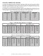
CHECKING TEMPERATURE SENSORS

The water heater temperature sensors (inlet water, outlet water, system water, and 

fl

 ue) are all resistance 

type devices. The following tables show the correct values for the sensors at various temperatures. Use an 
ohmmeter to read the resistance of the sensor at a known temperature. If the resistance of the sensor does 
not closely match its corresponding table, replace the sensor.
It is important to note that the 

fl

 ue and outlet water sensors have two temperature sensing devices in one 

housing. These devices are designated as S1a/S1b, outlet sensor and S3a/S3b, 

fl

 ue sensor. Please reference 

the wiring diagram in the XP Water Heater Instruction Manual for correct terminal location.

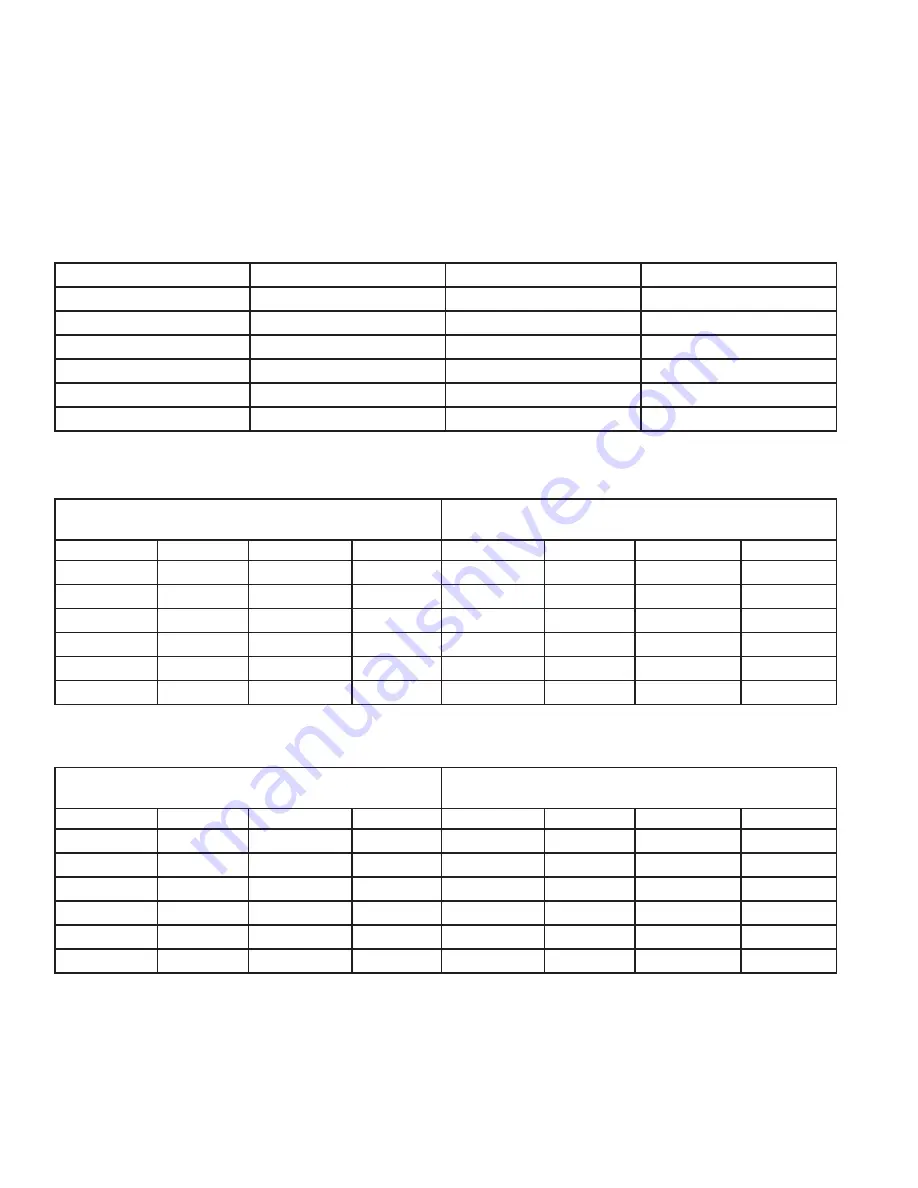
Table 11. Inlet System Sensor Resistance vs. Temperature

TEMPERATURE °F

RESISTANCE 

TEMPERATURE °F

RESISTANCE

50

18,780

158

1,990

68

12,263

176

1,458

86

8,194

194

1,084

104

5,592

212

817

122

3,893

--

--

140

2,760

--

--

Table 11.1 - Outlet Water Sensor Resistance vs. Temperature

S1A

(WIRE COLOR - R/BK AND Y)

S1B

(WIRE COLOR - G AND Y)

TEMPERATURE RESISTANCE

TEMPERATURE RESISTANCE TEMPERATURE RESISTANCE

TEMPERATURE

RESISTANCE

50

19,553

158

2,004

50

40,030

158

3,478

68

12,690

176

1,464

68

25,030

176

2,492

86

8,406

194

1,084

86

16,090

194

1,816

104

5,715

212

816

104

10,610

212

1,344

122

3,958

122

7,166

140

2,786

140

4,943

Table 11.2 - Flue Sensor Resistance vs. Temperature

S3A

(WIRE COLOR - W/B AND Y)

S3B

(WIRE COLOR - PR AND Y)

TEMPERATURE RESISTANCE

TEMPERATURE RESISTANCE TEMPERATURE RESISTANCE

TEMPERATURE

RESISTANCE

50

40,030

158

3,478

50

258,500

158

16,870

68

25,030

176

2,492

68

125,500

176

12,000

86

16,090

194

1,816

86

80,220

194

8,674

104

10,610

212

1,344

104

52,590

212

6,369

122

7,166

122

35,270

140

4,943

140

24,160

Содержание XWH 150

Страница 1: ...9 100274940_2000534998_Rev B 500 Tennessee Waltz Parkway Ashland City TN 37015 FOR MODELS XWH 150 THRU 800 INSTALLATION CONSIDERATIONS PRE SERVICE CHECKS CONSTRUCTION OPERATION SERVICE TROUBLESHOOTING...

Страница 2: ...Operation 8 Access Modes 8 Saving Parameters 8 SEQUENCE OF OPERATION 9 TOUCH SCREEN DISPLAY MENU ACCESS 11 TOUCH SCREEN DISPLAY PARAMETER ACCESS 13 PARAMETER TABLE 14 VIEWABALE AND CHANGEABLE CONTROL...

Страница 3: ...iction to perform a given task do not attempt to perform any of the procedures described in this service handbook If you do not understand the instructions given in this service handbook do not attemp...

Страница 4: ...ief Valve operation water discharged from the valve due to excessive pressure build up This condition is not covered under the limited warranty The Temperature Pressure Relief Valve is not intended fo...

Страница 5: ...be needed depending on the job site conditions Current NIOSH recommendations can be found on the NIOSH website at http www cdc gov niosh homepage html NIOSH approved respirators manufacturers and pho...

Страница 6: ...CE MODULE UIM TOUCH SCREEN DISPLAY Tank Temperature 71 F Operating Setpoint 184 F Status Ignition HELP DISABLE A O Smith XP MENU OFF GAS O N LCD Touch Screen Display Status Icons Main Menu Help Menu E...

Страница 7: ...BUILDING MANAGEMENT SYSTEM LOW VOLTAGE CONNECTION BOARD INLET TEMPERATURE SENSOR OUTLET TEMPERATURE SENSOR FLUE GAS SENSOR DAMPER PROVING SWITCH FLAME SENSOR LOW WATER CUTOFF BLOCKED CONDENSATE SWITCH...

Страница 8: ...TROL OUTPUTS LOW VOLTAGE CONNECTION BOARD CONTROL BOARD ALARM BELL DAMPER RELAY RUN TIME CONTACTS SEQUENCER BUILDING MANAGEMENT SYSTEM WATER HEATER PUMP IGNITER BLOWER GAS VALVE TOUCH SCREEN DISPLAY B...

Страница 9: ...f operation for water heating operation ACCESS MODES User The user can adjust tank target temperatures by accessing the Tank Temperature using the MENU option on the Touch Screen Display The date and...

Страница 10: ...switch and blocked drain switch must close The control starts the prepurge cycle The control starts the trial for ignition by energizing the spark electrode and opening the gas valve Tank Temperature...

Страница 11: ...s satisfied the control will de energize the gas valve The blower will continue to run for approximately 12 seconds during the postpurge The water heater pump will continue to run for its respective p...

Страница 12: ...tion Press the MENU options to get access to Main Menu which includes Temperatures Heater Status Display Settings Heater Information etc Use the appropriate Menu option to change unit settings or for...

Страница 13: ...uctions Status Icon Legend Operating States etc Table 2 Menus From The Display Panel Continued Operating Instructions Status Icon Legend Operating States Adjusting Operating Setpoint Change the Displa...

Страница 14: ...en Adjust the Tank Setpoint using the buttons on the Touch Screen Display to the desired temperature Select Accept button to save the desired temperature settings The UIM will save the desired tempera...

Страница 15: ...AR button YES NO YES YES Service Service Contact Info Contact Name YES NO YES YES Service Service Contact Info Contact Phone YES NO YES YES Circulation Pumps Circulation Pumps DHW Pump Delay YES NO YE...

Страница 16: ...ead Lag DHW Size Slave X YES NO YES YES Economy Mode Clock Economy Mode Clock Current Time YES YES YES YES Economy Mode Clock Current Date YES YES YES YES Economy Mode Clock Setpoint Adjustment YES NO...

Страница 17: ...er by accessing the Setpoint Offset parameter The temperature range of this parameter is 0 F 0 C to 10 F 30 C The default value is 4 F 6 C DISPLAY SETTINGS Backlight Delay This is the time in which th...

Страница 18: ...trol or the 0 10V input value received through ModBus The default value is INACTIVE BMS Type When programmed for BMS control through the 0 10V BMS input or through ModBus the 0 10V signal can be inter...

Страница 19: ...connected to the Leader water heater The default address is 1 Lead Lag Efficiency Enhancement Types There are two 2 options for the way a Lead Lag divides the load between its heaters The first is Lea...

Страница 20: ...at Lead Lag The water heater size parameters allow the installer to program the sizes based on the Lead Lag address This screen shows the Lead Lag address and the size of the water heater with that ad...

Страница 21: ...rol will abort short cycling and allow the water heater to fire This parameter can be changed by the installer by accessing the Short Cycling Differential parameter The temperature range of this param...

Страница 22: ...eckout and performance verification per Section 10 of this service handbook Flame inspection stable uniform Flame signal at least 10 microamps at high fire Clean the heat exchanger if flue temperature...

Страница 23: ...r system exhibit any unusual behavior 3 Remind the owner to follow the proper shutdown procedure and to schedule an annual maintenance 4 Inspect any problems reported by the owner and correct before p...

Страница 24: ...g any T P relief valve ensure that it is piped with its discharge in a safe area to avoid severe scald potential Please refer to the System Piping section of the XP Water Heater Instruction Manual bef...

Страница 25: ...ter wiring 1 Inspect all water heater wiring making sure wires are in good condition and securely attached Check control settings 1 Use the UIM control display to access MENU and check all parameter s...

Страница 26: ...assembly The water heater contains ceramic fiber materials Use care when handling these materials per the instructions on Page 3 of this Service Handbook Failure to comply could result in severe pers...

Страница 27: ...e the heat exchanger door must be replaced Consult factory for replacement heat exchanger door Kit 100173794 and 100173799 Check Delta T 1 Check the Delta T using Table 7 below as a reference Table 7...

Страница 28: ...ximum 132 VAC to water heater 3 Make sure all external limit controls are installed and operating Check the following 1 Wire connectors to control module are securely plugged in at the module and orig...

Страница 29: ...aker Check position of ON OFF switch Turn switch to the ON position Check 120 VAC through the ON OFF switch Check wiring harness connection between display board and main control board Connect harness...

Страница 30: ...um listed in the General Venting section of the XP Water Heater Instruction Manual Dirty damaged burner Refer to Page 24 in this Service Handbook for the burner removal and inspection procedure Clean...

Страница 31: ...eck water heater pump operation on a call for heat Check for closed valves or obstructions in the water heater piping Verify system is full of water and all air has been purged from the system Check v...

Страница 32: ...d cleaning procedures Replace if necessary Inspect the heat exchanger Refer to the Instruction Manual for removal and cleaning procedures Replace if necessary Faulty air pressure switch Replace switch...

Страница 33: ...are no obstructions Check for 24 VAC to the gas valve at the 2 pin connection on the side of the main control board during the ignition attempt If no voltage is present replace the main control board...

Страница 34: ...talled correctly and there are no obstructions Check for 24 VAC to the gas valve at the 2 pin connection on the side of the main control board during the ignition attempt If no voltage is present repl...

Страница 35: ...m Verify that the water heater is piped properly into the system Refer to the Instruction Manual for proper piping methods Check 120 vac to water heater pump motor on a call for heat If voltage is not...

Страница 36: ...30 lower or higher than what is being called for Vent air intake lengths exceed the maximum allowed lengths Check for proper lengths Check for obstruction or blockage in the vent air intake pipes or a...

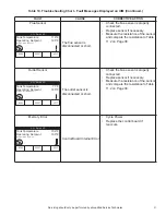
Страница 37: ...sensor Replace flue sensor if necessary Measure the resistance of the sensor and compare the resistance to Table 11 2 on Page 38 Outlet Temp Drift The outlet temp thermistor has exceeded the 10 degre...

Страница 38: ...is properly connected Replace sensor if necessary Measure the resistance of the sensor and compare the resistance to Table 11 2 on Page 38 Memory Error Control Board Internal Error Cycle Power Replac...

Страница 39: ...Inlet System Sensor Resistance vs Temperature TEMPERATURE F RESISTANCE TEMPERATURE F RESISTANCE 50 18 780 158 1 990 68 12 263 176 1 458 86 8 194 194 1 084 104 5 592 212 817 122 3 893 140 2 760 Table 1...

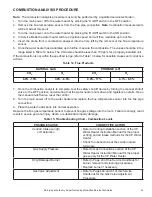
Страница 40: ...9 0 11 4 1 6 9 7 Once the combustion analysis is complete test the safety shutoff device by turning the manual shutoff valve to the OFF position and ensuring that the water heater shuts down and regi...

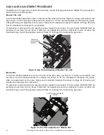
Страница 41: ...our 4 times If after four 4 adjustments and the combustion is still not within the specified range revisit the possible causes in Table 13 on Page 39 or replace the gas valve Model 400 Locate the thro...

Страница 42: ...the possible causes in Table 13 on Page 39 or replace the gas valve Models 600 800 Locate the throttle adjustment screw on top of the gas valve see Figure 12 Using an Allen wrench turn the screw a 1 4...

Страница 43: ...42 Servicing should only be performed by a Qualified Service Technician NOTES...

Страница 44: ...additional information contact A O Smith Corporation 500 Tennessee Waltz Parkway Ashland City TN 37015 Tech Support 800 527 1953 Parts 800 433 2545 www hotwater com Copyright 2019 A O Smith Water Hea...

Отзывы: