A.O. Smith Dre 120 Скачать руководство пользователя страница 3

DRE

Dimensions

DRE

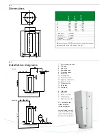
Installation diagrams

1   Pressure reducing valve
3   T&P valve

4   Stop valve

5   Non-return valve
6   Circulation pump

9   Drain valve
11  Isolating valve
14  Hot water outlets
15  Expansion relief valve
16  Expansion vessel

17  Three way valve

18  Water tank
19  Float valve

A   Cold water 

B   Hot water 

C   Return circulation 
E   Overfl ow pipe

H   Expansion vent pipe

A.O. Smith unvented 
system kits utilise 
combination valves

Further installation and 
connection details can be 
found in the Installation 

& Commissioning Manual.

A   


1465 

1570 

1610

B   


1410 

1530 

1580

D   


550 

640 

750

E   


690 

800 

910

M  


120 

100 

100

R   


100 

100 

100

S   


1210 

1310 

1380


1  Cold water   

1

1

/

4

-14 NPT

2  Hot water   

1

1

/

4

-14 NPT

4  Tank drain valve  

3

/

4

-14 NPT

5  T&P valve  

3

/

4

-14 NPT

6  Anode connection  Rp

3

/

4

Dimensions in mm. All DRE water heaters receive a three years 
warranty on the tank and one year on parts.

DRE 52 

DRE 80 

DRE 120

Vented

Unvented

Содержание Dre 120

Страница 1: ... own control thermostat adjustable 49 82 C and a manually resetable high limit thermostat Cascade control of the elements for more efficient and faster heating up times All elements and thermostats are fuse protected PermaGlas Ultra Coat second generation glass coating technology helps to prevent corrosion Replaceable magnesium anode Safety float switch Optional ancillaries Unvented kits Destratifica...

Страница 2: ...26 1020 1314 90 min T 50 C l 416 641 1090 512 737 1186 1635 656 881 1330 1779 120 min T 50 C l 494 796 1399 590 892 1495 2099 734 1036 1639 2243 Continuous T 50 C l h 155 310 619 155 310 619 929 155 310 619 929 Heating up time T 50 C min 78 39 19 116 58 29 19 174 87 44 29 30 min T 55 C l 238 301 428 325 388 515 642 456 519 646 773 60 min T 55 C l 308 442 709 396 529 797 1064 526 660 927 1195 90 mi...

Страница 3: ...nsion vent pipe A O Smith unvented system kits utilise combination valves Further installation and connection details can be found in the Installation Commissioning Manual A 1465 1570 1610 B 1410 1530 1580 D 550 640 750 E 690 800 910 M 120 100 100 R 100 100 100 S 1210 1310 1380 1 Cold water 11 4 14 NPT 2 Hot water 11 4 14 NPT 4 Tank drain valve 3 4 14 NPT 5 T P valve 3 4 14 NPT 6 Anode connection ...

Страница 4: ... website A Main terminal B Solenoid D Overheat thermostat E Electric element H Float switch K Safety relay L Fuse M Transformator 1 Black 2 Red 3 Blue 4 Brown 5 White For the parts numbers of components please refer to the Maintenance and accessories chapter DRE Electrical diagrams 3 elements 6 elements 9 elements ...

Отзывы: