background image


10 

QCOM Tool v1.6                            

Copyright © 5GHUB.US


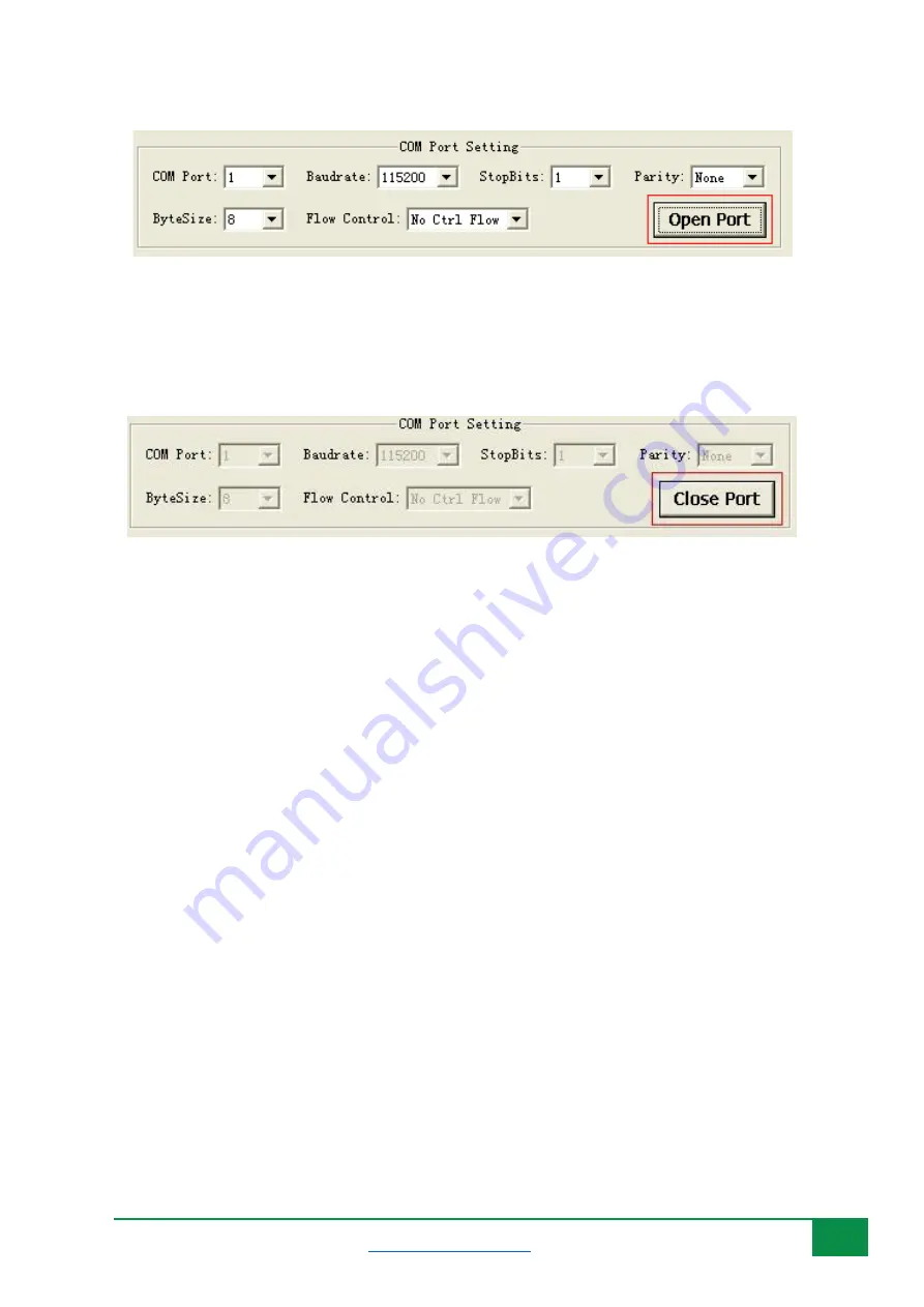
Figure 9: Clicking “Open Port” button. 


Click “

Close Port

” to close the selected COM port. Please refer to Figure 10. 


Figure 10: Clicking “Close Port” button. 


4.3


Send Data 

To send data from the QCOM tool, follow the following steps: 

1)


Red 

area is used to input data which would be sent. 

2)


Green 

area is used to choose file needed and send a whole file.  

3)


Blue 

area is used to save received data as a file. 

4)


DTR: Enable the DTR pin of COM port.


5)


RTS: Enable the RTS pin of COM port. 

6)


View File: Show the data of the file which has been sent.  

7)


Show Time: Show the time of each received data. 

8)


HEX String: The input string is HEX string. 

9)


Show in HEX: The received data is shown in HEX.  

10)


Send with Enter: Send data with “

Enter

”. 

11)


Clear Information: Clear all received data and status information.  

12)


Send Command: Start to send the data which you input. 

13)


Select File: Select the file which would be sent. 

14)


Send File: Start to send the file that you have selected.  

15)


Save Log: Select the file of which the Log data was saved. 


Содержание QCOM tool

Страница 1: ...1 QCOM Tool v1 6 Copyright 5GHUB US QCOM TOOL USER GUIDE QCOM Tool User Guide ...

Страница 2: ...Document The purpose of this document is to explain the QCOM tool and how to use it with different wireless modules such as BG96 B95 BG77 EG91 EG95 or Raspberry PI HAT Document History Version Author Date Description A 5G HUB 10 05 2020 Initial Document ...

Страница 3: ... the Document 2 Document History 2 1 Introduction 4 2 Install LTE GNSS Windows Driver 5 3 Use QCOM tool with BG96 BG95 EG91 EG95 6 4 How to Use the QCOM Tool 8 4 1 COM Port Configuration 8 4 2 Open and Close COM Port 9 4 3 Send Data 10 4 4 Send Data Continuously 11 ...

Страница 4: ...upports the following OS Window 10 Windows 95 Windows 98 Windows 2000 Windows ME Windows XP This document is applicable to all GSM UMTS LTE and GNSS modules Install the following tools from the GitHub repository LTE GNSS driver 5G NB IoT Driver at master 5ghub 5G NB IoT github com QCOM Tool 5G NB IoT Tools at master 5ghub 5G NB IoT github com ...

Страница 5: ... View Follow the following steps 1 Insert a USIM card into the USIM card slot on the hardware board 2 Connect a USB cable between the hardware board and the computer as in the following diagram Note the hardware board is an example and other USB dongle or Raspberry PI HAT can be used You can also use different antennas if needed If you are using the HAT board with any of the BG96 BG95 EG95 EG91 mi...

Страница 6: ... use the QCOM tool with LTE GNSS modem connect the computer USB port to the USB port on the hardware board and make sure all modem serial ports are enumerated in the Windows device manager as in figure below The serial ports below can be used for the following purposes USB Modem The USB modem interface is used for AT commands data transmission GNSS data and NMEA sentences output USB AT Port It is ...

Страница 7: ... the serial port number uses as in format COMXX If the USB Modem port is used you can find its COM port number by right click on it select Properties then select Modem You will find the port number displayed for this USB modem It shows up as COM47 in the figure below You can use this port number in QCOM tool Figure 4 Port number for the USB modem ...

Страница 8: ...l Figure 5 QCOM tool graphical user interface GUI Red area displays the received data Blue area displays status information Purple area is used to send data or files Green area is used to send data continuously 4 1 COM Port Configuration According to the connection between PC and the hardware board select the right serial port as shown Figure 6 Select the COM port number corresponds to either the ...

Страница 9: ... rate Please refer to Figure 7 Figure 7 Selecting Baud rate Choose appropriate Stop Bits Parity Byte Size and Flow Control shown as Figure 8 Figure 8 Selecting Other parameters for the COM port 4 2 Open and Close COM Port Click Open Port to open the selected COM port Please refer to Figure 9 ...

Страница 10: ...ta as a file 4 DTR Enable the DTR pin of COM port 5 RTS Enable the RTS pin of COM port 6 View File Show the data of the file which has been sent 7 Show Time Show the time of each received data 8 HEX String The input string is HEXstring 9 Show in HEX The received data is shown inHEX 10 Send with Enter Send data with Enter 11 Clear Information Clear all received data and status information 12 Send C...

Страница 11: ... Choose All Commands Enable all available commands which would be sent 5 HEX The input string is HEX string 6 Enter Send data with Enter 7 Delay Delay time for each data 8 Delay Time Default delay time 9 Run Times The times of sending all selected data continuously 10 Run Start to send all selected data continuously 11 Stop Stop sending all selected data continuously 12 Save As Script Save all dat...

Страница 12: ...Figure 13 shows how to connect the QCOM tool to USB modem on port COM47 Once you specify the COM port as 47 Baud rate as 115200 click Open Port You can exchange AT commands with the modem including registering on mobile operator network query the GPS location signal strength ...

Страница 13: ...13 QCOM Tool v1 6 Copyright 5GHUB US Figure 13 Connecting QCOM tool to USB modem on port COM47 The following shows more examples of using AT commands Figure 14 More AT commands examples using QCOM tool ...

Страница 14: ...e time you can launch another instance of QCOM tool and connect to the USB NMEA Port COM49 Once you open the port to COM49 you can see all GNSS NMEA sentences output as in the following figure Figure 15 Connecting QCOM tool to USB NMEA port on COM49 ...

Отзывы: