4tronix Ultimate Initio kit Скачать руководство пользователя страница 3

It won't damage it if you connect them differently, but the example programs won't go the 
direction that you would expect 


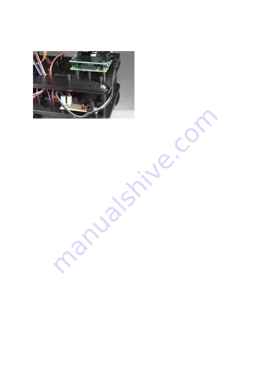
Plug the Black/White cable with the DC Jack into the left-most pins on the switch PCB on 
Initio and the DC Jack end into the Pirocon as shown above. 

Check all the wiring again very carefully, then now is a good time to see if the Pi powers up 
and you can control the motors. 

Use 6xAA batteries. These should be good quality rechargeable batteries. We recommend 
Energizer Extremes or Eneloops 

Connect a monitor, keyboard and mouse to the Raspberry Pi, plug in your SD card and switch 
on. The green light near the On/Off switch should turn on, the LEDs on the Pi should start 
flashing and the booting sequence should appear on the monitor. If not, switch off and double 
check the wiring. 

Instead of using the batteries, you can plug a micro-USB cable directly into the connector on 
the Pi. This is an excellent way to get started and allows you to test everything (except the 
motors, which may turn but only slowly) without using batteries. 


Содержание Ultimate Initio kit

Страница 1: ...gnal strength and resolve issues with marginal IR sensors including the wheel sensors on the Initio Quickstart Pinout Description If you use the recommended iBoost64 input signal booster then we can connect the 8 I O signals as follows Pin 7 Left Obstacle sensor Pin 11 Right Obstacle sensor Pin12 Left Line sensor Pin 13 Right Line sensor Pin 15 Left Wheel sensor 1 Optional Pin 16 Right Wheel senso...

Страница 2: ...above is suitable for a Raspberry Pi Model B Model A or Raspberry Pi 2 Model B Use the hole in the centre if using a Model A or Model B Push the Pirocon carefully onto the GPIO pins of the Raspberry Pi ensuring the pins are placed correctly as shown in the photo above Connect the motor wires as shown Red Black Black Red ...

Страница 3: ...ould be good quality rechargeable batteries We recommend Energizer Extremes or Eneloops Connect a monitor keyboard and mouse to the Raspberry Pi plug in your SD card and switch on The green light near the On Off switch should turn on the LEDs on the Pi should start flashing and the booting sequence should appear on the monitor If not switch off and double check the wiring Instead of using the batt...

Страница 4: ...g collars Screw one onto the body of the sensor leaving room at the front for the second one Push the sensor through from the rear of the mounting bracket and screw on the second collar Feed the wires up through the holes in the top plate Repeat for the second side ...

Страница 5: ... below Left sensor to Pin 7 marked x07 or 04 Right sensor to Pin 11 marked x11 or 17 The wire colours from the obstacle sensor are Red 5V Black Gnd White or Yellow Signal Make sure you connect them to the correct pins on the Pirocon or iBoost64 ...

Страница 6: ...n Red Orange Yellow this is for the Ultrasonic Sensor Green Blue Purple this is for the Left Line Sensor Grey White Black this is for the Right Line Sensor Next prepare the two Line Sensors and 2 of the 3x8PB screws as shown Screw the line sensors in position as shown using the screwhole in the middle of the circuit board ...

Страница 7: ... Sensor Note some sensors have the pins in order 5V Signal Gnd other have them in order Signal 5V Gnd make sure you know which wire colour is connected to which Connect the sensors to the Pirocon or iBoost64 shown below Left sensor to Pin 12 marked x12 or 18 Right sensor to Pin 13 marked x13 or 27 ...

Страница 8: ...bled one then please visit the assembly instructions here opens in new window Take 4 of the 2 0x6PB screws these are the smallest ones in the packet and there are 6 of them Screw the base of the pan tilt assembly to the upper plate in the position shown Rotate the pan tilt carefully left and right to access the screw holes ...

Страница 9: ...e they are connected correctly Black Gnd Red 5V Orange or White Signal 5 Connecting the Ultrasonic Sensor For this you will need the mounting plate saddle clamp and the final 2 of the 2 0x6PB screws used in step 4 Push the 4 way 30cm female female cable that you made in Step 3 onto the top of the ultrasonic sensor Brown Gnd Red Echo Orange Trig or Ping Yellow 5V or VCC ...

Страница 10: ...bly as shown above Note that you can purchase additional clip on mounts so you could mount a camera on one and simply clip it off to change from Ultrasonic to Camera Connect the other end of the cable into the ultrasonic pins located between the 2 motor terminals Ensure that Brown is Gnd and they are in the order as shown ...

Страница 11: ...ar with the operation of the rest of the robot If you want to fit them use Pins 15 and 16 marked x15 x16 or 22 23 and note that the silk screen on the board has these swapped over For each Wheel Sensor connect Black to Gnd Red to 5V Orange or Brown to the selected pin in fact each wheel has 2 sensors that are slightly out of phase so you can get direction of travel from them but you will then need...

Отзывы: