
1. Check the box contents
The Aprisa SR+ is shipped to you in a box containing the following:
Aprisa SR+ radio fitted with power connector
USB Cable USB A to USB micro B, 1m
Used for Command Line Interface management - see Aprisa SR+ User
Manual
2. Install the Aprisa SR+ radio and connect the protection earth
The Aprisa SR+ has four threaded holes (M4) in the base and two holes (for M5 screws) through the enclosure for mounting. Mounting options
include:
DIN rail mounting with the Aprisa SR+ Mounting Bracket (optional accessory part number ‘APSB-MBRK-DIN’)
Wall and rack shelf mounting
Outdoor enclosures
The Aprisa SR+ mounting options are shown below:
The Aprisa SR+ has an earth connection point on the top left and the top right of the enclosure.
Use the supplied M4 screws to earth the enclosure to a protection earth.
The antenna feeder cable should use grounding kits for lightning protection as specified or
supplied by the coaxial cable manufacturer to properly ground or bond the cable outer.
Warning:
If the Aprisa SR+ is operated in an environment where the ambient temperature exceeds 50°C, the Aprisa SR+ must be installed
within a restricted access location to prevent human contact with the enclosure heatsink.
Note:
The Aprisa SR+ radio operates within frequency bands that require a site license be issued
by the radio regulatory authority with jurisdiction over the territory in which the equipment is
being operated. It is the responsibility of the user, before operating the equipment, to ensure
that where required the appropriate license has been granted and all conditions attendant to that
license have been met.
Hereby, 4RF Limited declares that the Aprisa SR+ digital radio is in compliance with Directive
2014/53/EU. The full text of the EU declaration of conformity is available at the internet address
http://www.4rf.com/library/en.
3. Connect the antenna and apply power to the Aprisa SR+ radio
Connect the antenna to the antenna port TNC female connector. If the antenna is not available, terminate the ‘TX / Ant’
port with a TNC male 50 ohm terminator (10 Watts min).
Warning:
Do not directly connect the two radio antenna ports without attenuation of at least 40 dB. The receiver can be
damaged if signals greater than +10 dBm are applied to the antenna port.
The Aprisa SR+ is operated from a DC source of voltage b10 VDC and +30 VDC (negative earth) and consumes up
to 35 Watts. External power supplies are available from 4RF as accessories (see the Aprisa SR+ User Manual).
The power connector (Molex 2 pin female) is supplied fitted to the radio. Wire your power source to the power connector
(- / +) and plug the connector into the radio. The connector screws should be fastened to secure the connector.
Note:
The radio fuses will blow if the connected power supply is over voltage or the polarity is reversed. Two spare fuses
are located inside the enclosure (see the ‘Spare Fuses’ section of the Aprisa SR+ User Manual).
Turn your power source on. The radio LEDs will flash orange for one second and then the OK, MODE, AUX LEDs will light solid green and the TX
and RX LEDs will flash red. This is because the factory default Terminal Operating Mode for all Aprisa SR+ radios is set to Remote Station.
When the radio has been configured and has registered with the network, the TX and RX LEDs will be solid or flash green if the network is
operating correctly.
The Aprisa SR+ radio is ready to operate.
Warning:
On link operation, RF energy is radiated from the antenna. Do not stand in front of the antenna.
4. Connect to the Aprisa SR+ radio
The Aprisa SR+ has a factory default IP address of 169.254.50.10 with a subnet mask of 255.255.0.0. The Aprisa SR+ protected station has a
factory default IP address of 169.254.50.10 for radio A and 169.254.50.20 for radio B with a subnet mask of 255.255.0.0.
Each radio in the Aprisa SR+ network must be setup with a unique IP address on the same subnet.
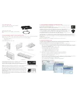
If the IP address of the radio is unknown, it can be changed via the Command Line Interface on the radio MGMT USB port:
Connect your PC USB port to the Aprisa SR+ MGMT USB port. USB to UART Bridge VCP Drivers are required to connect the radio USB
port to your PC. You can download and install the relevant driver from https://www.silabs.com/products/development-
tools/software/usb-to-uart-bridge-vcp-drivers.
Login to the radio with the default login ‘admin’ and password ‘admin’.
At the command prompt >> type ‘cd APRISASR-MIB-4RF’ and enter.
- type ‘set termEthController1IpAddress xxx.xxx.xxx.xxx’ and enter.
- type ‘set termEthController1SubnetMask 255.255.0.0’ and enter.
- type ‘set termEthController1Gateway xxx.xxx.xxx.xxx’ and enter.
If the IP address of the radio is known or is the default IP address, it can be changed via the Ethernet port:
Setup your PC for a compatible IP address e.g. 169.254.50.1 with a subnet mask of 255.255.0.0.
Connect your PC network port to one of the Aprisa SR+ Ethernet ports.
Open a browser and enter http://169.254.50.10.
Note: The Aprisa SR+ has a Self Signed security certificate which may cause the browser to prompt a certificate warning. It is safe to
ignore the warning and continue. The valid certificate is ‘Issued By: 4RF-APRISA’ which can be viewed in the browser.
Login to the radio with the default login ‘admin’ and password ‘admin’.
Change the IP address, Subnet mask and Gateway to network compatible IP addresses.