Calibrating Lockout Time for Gate Out
On the back of the
PI
, there is a trim
pot labelled CAL LOCK-OUT. This trim
pot controls how quickly the
PI
is able
to re-trigger. It has been calibrated to
a period of 100ms, which is equivalent
to 10Hz, ten drum hits per second, or
600BPM. This is known as the “lock-
out period”.
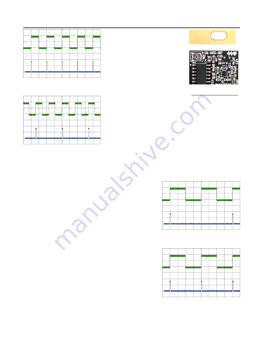
Figure 14
shows a 10Hz square wave
in green being sent to the input of the
PI
, and the
Gate
output of the
PI
in
blue. The
Sustain
knob is set to
minimum. Notice both signals are at
the same frequency of 10Hz.
In
Figure 15
the frequency of the green
square wave has increased to around
12Hz. The
PI
Gate
output in blue is
now half the frequency of the input.
This happens because the
PI
has been
calibrated to ignore frequencies higher
than 10Hz in order to prevent misfires
and undesired hits. The
PI
is still synchronized with the input
signal, but it is outputting half the tempo.
Depending on your preference, the lock-out period can be adjusted. For example, if you find the
PI
is
not responding to very rapid drum hits, you can turn the CAL LOCK-OUT trim pot counter-clockwise a
small amount. This will allow the
PI
to respond to faster drum hits. Keep in mind that this adjustment will
also increase the potential for extra undesired triggers on the gate output.
On the other hand, if you typically use an input signal with long
decays or less frequent hits, you can turn the trim pot clockwise
to increase the lock-out period and prevent undesired gates.
This is similar to adjusting the
Sustain
knob in order to clean up
drums with a long decay, but the trim pot doesn’t change the
pulse width of the
Gate
output. Setting the lock-out period with
the trim pot is useful in
Gen
.
mode, as it enables you to adjust
the
Sustain
pot freely to control the envelope shape, without
worrying about undesired triggers.
The following procedure explains how to set a precise lock-out
period. You’ll need a frequency counter, oscilloscope, or some
way to detect frequency or fast BPMs. We’ll use five hits per
second, or 5Hz as our desired lock-out frequency.
1. Tune a square wave or clock signal to the desired frequency
and patch it into the
PI
’s input jack. In
Figure 16
the input
signal is a 5Hz square wave in green.
2. Turn
Sustain
down fully, and adjust
Sensitivity
so that the
PI is firing pulses out the
Gate
jack.
3. Adjust the CAL LOCK-OUT trim pot until the
PI
gate output
is half the frequency of the input (2.5Hz). In
Figure 16,
the
blue signal is the
Gate
output.
4. Slowly
turn the trim pot counter-clockwise until the
frequencies match, as shown in
Figure 17
.
At this point, the lock-out period will be 5Hz and no frequencies
faster than this will generate pulses. You can test to make sure
this was done correctly by increasing the frequency of the input signal and verifying that
the
PI
’s output frequency jumps down to half the input frequency.
Page of
13
16
Figure 14
Figure 15
Figure 17
Figure 16
The trim pot is small
and delicate, so
adjust it gently using
the proper sized
screwdriver (2.0mm
flat-head or #00
Phillips screwdriver).


