background image


gen4-uLCD-XXPT - GETTING STARTED MANUAL


8  


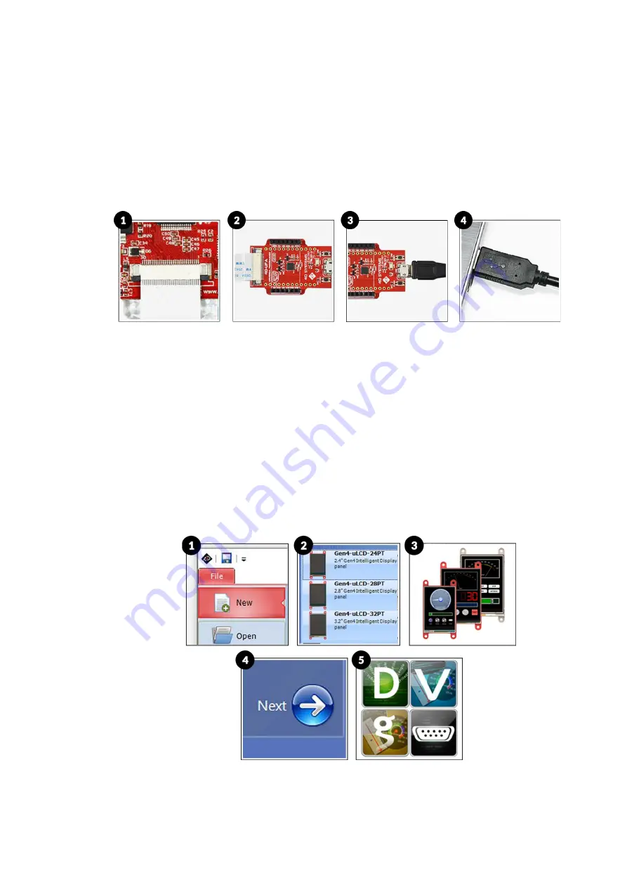
Option C – Using the 4D-UPA 


1.


Connect one end of the FFC to your module’s 30 way ZIF socket with 

the metal contacts on the FFC facing up on the latch. 

2.


Connect the other end of the FFC to the 30-way ZIF socket on the 4D-

UPA with the metal contacts on the FFC facing up on the latch. 

3.


Connect the USB-Micro-B Cable to the 4D-UPA. 

4.


Lastly, connect the other end of the USB-Micro-B Cable to the 

computer. 


Let WS4 Identify the Display Module 

After following the appropriate set of instructions in the previous section, 

you now need to configure and setup Workshop4 to make sure that it 

identifies and connects to the correct display module. 
1.


Open Workshop4 IDE and create a new project. 

2.


Select the display module you’re using from the list. 

3.


Select your desired orientation for your project. 

4.


Click next. 

5.


Choose a WS4 Programming Environment. Only the compatible 

programming environment for the display module will be enabled. 


Содержание gen4-uLCD-28PT

Страница 1: ...gen4 uLCD XXPT GETTING STARTED MANUAL 1...

Страница 2: ...amming Cable Using the uSB PA5 II Using the 4D UPA Let WS4 Identify the Display Module 09 Getting Started with a Simple Project 15 Workshop4 Pro 16 Application Notes 17 Reference Documents 19 Glossary...

Страница 3: ...ystems Picaso graphics processor which offers an array of functionality and options for the designer integrator user Intelligent display modules are low cost embedded solutions used in various applica...

Страница 4: ...4D Programming Cable uUSB PA5 II Programming Adaptor 4D UPA To use any of the programming modules the corresponding driver must first be installed in the PC You may refer to the product page of the gi...

Страница 5: ...es four development environments for the user to choose based on application requirements or even user skill level Designer ViSi Genie ViSi and Serial Workshop4 Environments Designer This environment...

Страница 6: ...s for connecting the display to the PC There are three 3 options of instructions under this section as shown in the image below Each option is specific to a programming module Follow only instructions...

Страница 7: ...with the assistance of the supplied ribbon cable 4 Connect the other end of the 4D Programming Cable to the computer Option B Using the uUSB PA5 II 1 Connect one end of the FFC to your module s 30 wa...

Страница 8: ...ect the other end of the USB Micro B Cable to the computer Let WS4 Identify the Display Module After following the appropriate set of instructions in the previous section you now need to configure and...

Страница 9: ...ropdown list 7 Click on the RED Dot to start scanning for the display module A YELLOW dot will show while scanning Make sure that your module is connected properly 8 Lastly a successful detection will...

Страница 10: ...ject consists of a slider an input widget controlling a gauge an output widget The widgets can also be configured to send event messages to an external host device through the serial port Create a New...

Страница 11: ...e of widget that you want to use In this case the slider widget is selected Simply drag and drop the widget towards the What You See Is What You Get WYSIWYG section Add a Gauge Widget To add a gauge w...

Страница 12: ...widget is released On the other hand the OnChanging event is continuously triggered while an input widget is being touched In this example the OnChanging event is used Set the event handler by clickin...

Страница 13: ...during runtime The graphics processor will then render the widgets on the display At this point WS4 generates the required graphics files and will prompt you for the drive to which the microSD card i...

Страница 14: ...nt out by the display module to the serial port This tool is called GTX which stands for Genie Test eXecutor This tool can also be thought of as a simulator for an external host device The GTX tool ca...

Страница 15: ...ems display Genie Magic brings the ability to add standard 4DGL code to various points within the ViSi Genie environment This enables you to have all the advantages of ViSi Genie but with the new abil...

Страница 16: ...ou Get screen ViSi 4D AN 00001 ViSi Genie Getting Started First Project for Picaso Display Modules The simple project developed in this application note demonstrates basic touch functionality and obje...

Страница 17: ...graphics oriented language allowing rapid application development An extensive library of graphics text and file system functions and the ease of use of a language that combines the best elements and...

Страница 18: ...gen4 uLCD XXPT GETTING STARTED MANUAL 18 NOTES...

Страница 19: ...hardware having one or more recessed holes with electrical terminals inside 5 Micro USB cable a type of cable used to connect the display to a computer 6 microSD Card a type of removable flash memory...

Страница 20: ...ion 6 Image Files are graphics files generated upon program compilation that should be saved into the microSD Card 7 Object Inspector a section in Workshop4 where the user can change the properties of...

Отзывы: