background image

PAGE 16

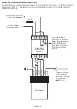
SPEED RELAY WIRING DIAGRAM (SIMPLIFIED) - 

The diagram below is a simplified wiring diagram for connecting the WDA sensor to a 4B Rotech Speed 

Relay (Model SR2V5-1).  See speed relay and other applicable instructions for complete set-up and 

installation information.

WDA Sensor

1 2 3 4 5 6

7 8 9 10 11 12

Speed Relay

Control Module

SR2V5-1

X

WHITE

ORANGE

RED

BLUE

BLACK

GREEN

N

L

Fuse 2A

110 VAC When Running

0 VAC When Stopped

110 VAC Supply

From Motor Starter

No Connection

Continuous Output

0 VDC Running

12/24 VDC Stopped

Insulate And Do 

NOT

 Connect

Contacts Shown In 

Underspeed / Stopped 

State.  Relay Energized 

When Running And 

De-energized If Speed 

Falls Below The Set 

Speed.

Содержание HTAS1V34

Страница 1: ...www go4b com usa WDA Sensor BELT ALIGNMENT MOTION BROKEN SLACK CHAIN MONITOR INSTALLATION INSTRUCTIONS OPERATION MANUAL Part No WDA3V34C APPROVED Class II Div 1 C US...

Страница 2: ...l cause severe injury or death Lockout power before removing cover or inspection door DANGER Exposed buckets and moving parts will cause severe injury or death Lockout power before removing cover or i...

Страница 3: ...DIMENSIONS Page 7 INSTALLATION BUCKET ELEVATOR Page 8 BUCKET ELEVATOR PLACEMENT DIAGRAMS Page 9 12 INSTALLATION CONVEYORS Page 13 14 STANDARD WIRING DIAGRAMS Page 15 16 TESTING COMMISSIONING Page 17 S...

Страница 4: ...asked 4B to perform these tasks B All installation and wiring must be in accordance with Local and National Electrical Codes and other standards applicable to your industry Please see the article Haz...

Страница 5: ...tion work at the facility hours of operation animal or insect infestation and the real world experience of knowing how your employees perform their jobs The personnel or person you select to install o...

Страница 6: ...uminium The WDA can detect ferrous steel elevator buckets from the side of the elevator leg or through the elevator belt from the back of the leg For plastic elevator buckets the steel elevator bolts...

Страница 7: ...ometer Sensing Range Adjustment Screw 9 ft Cable ALL DIMENSIONS IN INCHES 4 1 16 3 7 16 4 1 16 3 7 16 1 5 16 x 4 2 6 1 16 5 3 16 7 8 2 LED 1 2 Inch NPT Threaded Entry Sensor Depth Adjustment Bolt Sens...

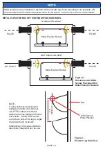
Страница 8: ...al or use the bracket itself by centering on the existing 2 1 4 inch 57 mm hole For side mounting of steel buckets Option 1 make sure that the belt is centered on the pulley and install a sensor on ea...

Страница 9: ...vator leg to target the elevator bolts used to secure the plastic buckets Figure 6 X X Mount WDA sensor within a few feet of the pulley or as close to this position as possible Figure 1 Typical WDA Se...

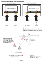
Страница 10: ...buckets and bolts non ferrous use PTFE coated steel fender washers ferrous between the belt and bucket Mount WDA sensor on the back side of the leg to target the ferrous bolts washers Alternatively 40...

Страница 11: ...NTING DIAGRAMS METAL ELEVATOR BUCKETS WITH CLOSE VERTICAL CENTERS Figure 5 illustrates the optimal WDA sensor placement for elevator buckets with close vertical spacing This placement allows for the m...

Страница 12: ...Of Leg 1 2 in to 1 in Plastic Elevator Bucket Approximately 1 1 2 inches Bolt Head Elevator Trunking WDA Mounting Block WDA Sensor Potentiometer Sensing Range Adjustment Screw Figure 7 WDA Sensor Inst...

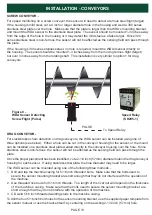
Страница 13: ...ng for the sensor or the mount can be installed on a stainless steel plate welded directly to the conveyor housing over the hole Since stainless steel is non ferrous the sensor will not be affected as...

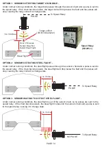
Страница 14: ...lt passes through the sensor s field and a pulse is sent to the speed relay If the chain becomes slack the target bolt will drop below the field and the pulses will stop causing the relay contact to c...

Страница 15: ...ody the wiring process is outline below RED BROWN Supply VDC BLACK BLUE Supply VDC GREEN GREEN Ground YELLOW ORANGE Control BLUE BLACK Pulsed Output WHITE Continuous Output WDA3 WDA1 To use the intern...

Страница 16: ...d installation information WDA Sensor 1 2 3 4 5 6 7 8 9 10 11 12 Speed Relay Control Module SR2V5 1 X WHITE ORANGE RED BLUE BLACK GREEN N L Fuse 2A 110 VAC When Running 0 VAC When Stopped 110 VAC Supp...

Страница 17: ...ler WARNING If the system does not alarm as required then remove the machine from service until the problem has been diagnosed and corrected TESTING AND COMMISSIONING 1 Check that the unit is correctl...

Страница 18: ...aring temperature pulley alignment and plugged condition monitoring for bucket elevators and conveyors A 3 5 LCD screen displays the entire system status at a glance WDA High Temperature Sensor HTAS1V...

Страница 19: ...DUE TO PRODUCT MISUSE ABUSE OR MISAPPLICATIONS AS AUTHORIZED BY LAW 4B SPECIFICALLY DISCLAIMS ALL WARRANTIES THAT THE PRODUCT IS FIT OR MERCHANTABLE FOR A PARTICULAR PURPOSE 3 NO WARRANTY BY SAMPLE OR...

Страница 20: ...frica Tel 27 0 11 708 6114 Fax 27 0 11 708 1654 4B AUSTRALIA Unit 1 18 Overlord Place Acacia Ridge Queensland 4110 Australia Tel 61 0 7 3711 2565 Fax 61 0 7 3711 2574 4B COMPONENTS LTD 625 Erie Avenue...

Отзывы: