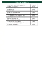


1. CUSTOMER SAFETY RESPONSIBILITIES
Page 4 - 5
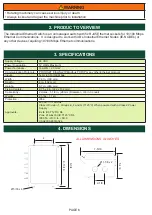
2. PRODUCT OVERVIEW
Page 6
3. SPECIFICATIONS
Page 6
4. DIMENSIONS
Page 6
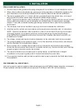
5. INSTALLATION
Page 7
6. ELECTRICAL CONNECTION
Page 8
7. WIRING DIAGRAMS
Page 10
7.1 SUPPLY VOLTAGE WIRING (24 VDC)
Page 10
7.2 NETWORK BLOCK DIAGRAM
Page 10
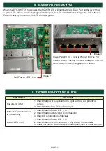
8. IE-SWITCH OPERATION
Page 11
9. TROUBLESHOOTING GUIDE
Page 11
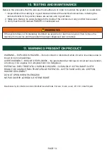
10. TESTING AND MAINTENANCE
Page 12
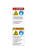
11. WARNINGS PRESENT ON PRODUCT
Page 12
12. PRODUCT WARRANTY
Page 15
TABLE OF CONTENTS
Содержание ETH-SWITCH1V4C-5P
Страница 9: ...PAGE 9 Output 4 Output 2 Output 3 Output 1 Input Power Earth Ground Image 1 ...
Страница 13: ...PAGE 13 END USER NOTES ...
Страница 14: ...PAGE 14 END USER NOTES ...