


【
Relay Connection
】
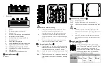
This device provides 1 M12 D-Coded 4-Pin slot
(female) for relay output. R1 and R2 is a pair of
normally open contacts of device alarm relay.
They are open circuit in normal non alarm state,
closed when any alarm information occurs.
Such as: it's closed when power off, and send out alarm. This
series switches support 1 channel relay alarm information
output, support DC power alarm information or network
abnormal alarm output, it can be connected to alerting lamp,
alarm buzzer, or other switching value collecting devices for
timely warning operating staffs when alarm information occurs.
The pin definitions of relay are as follows:
No.
1
2
3
4
Definiton
R1
R2
NC
NC
【
Console Port Connection
】
This device provides 1 program debugging port
based on RS232, which could be connected to
PC for device CLI command management. The
interface adopts M12 D-Coded 4-pin slot
(female). The pin definitions of M12 are as follows:
No.
1
2
3
4
Definition
TX
RX
NC
GND
Description
RS-232
sending
signal
RS-232
receiving
signal
Reserved
Ground
【
Communication Interface Connection
】
M12 100M Copper Port
This device provides 8 10/100Base-T(X) ports.
The interface type is M12 D-Coded 4-pin slot
(female). The pin definitions of M12 are as
follows:
No.
Definition
Description
1
TD+
100M Ethernet transmitted
signal Positive
2
TD-
100M Ethernet transmitted
signal Negative
3
RD+
100M Ethernet received
signal positive
4
RD-
100M Ethernet received
signal negative
M12 Gigabit Copper Port
This
device
provides
4
10/100/1000Base-T(X)
interfaces.
The
interface type is M12 A-Coded 8-Pin slot
(female) and its pin definitions are as follow:
No.
Definition
Description
1
D0+ (DA+)
The first group of bi-directional
data of Gigabit Ethernet
positive
2
D0- (DA-)
The first group of bi-directional
data of Gigabit Ethernet
negative
3
D1+ (DB+)
The second group of
bi-directional data of Gigabit
Ethernet positive
4
D1- (DB-)
The second group of
bi-directional data of Gigabit
Ethernet negative
5
D3+ (DD+)
The fourth group of
bi-directional data of Gigabit
Ethernet positive
6
D3- (DD-)
The fourth group of
bi-directional data of Gigabit
Ethernet negative
7
D2- (DC-)
The third group of
bi-directional data of Gigabit
Ethernet negative
8
D2+ (DC+)
The third group of
bi-directional data of Gigabit
Ethernet positive
【
Checking LED Indicator
】
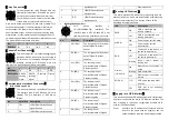
This device provides LED indicators for monitoring the work
status of the device, which has simplified the troubleshooting
process comprehensively. The function of each LED is
described in the table as below:
LED
Status
Description
PWR
ON
PWR is connected and
running normally
OFF
PWR is disconnected and
running abnormally.
ALARM
ON
Power supply, port link alarm
OFF
Power supply, port link
without alarm
RUN
ON
The device is powered on or
the device is abnormal.
OFF
The device is powered off or
the device is abnormal.
Blinking
Blink 1 time/s, system is
running well.
Link/Act
(1-8/G1-G4)
ON
Ethernet port connection is
active.
Blinking
Data transmitted
OFF
Ethernet port connection is
inactive.
POE(1-8)
ON
POE port is powering other
devices.
OFF
POE port is not powering
other devices.
【
Logging in to WEB Interface
】
This device supports WEB management and configuration.
Computer can access the device via Ethernet interface. The
way of logging in to device
’s configuration interface via IE
browser is shown as below:
Configure the IP addresses of computer and the
Step 1
device to the same network segment, and the
network between them can be mutually accessed.


