
the top into DIN-Rail.
Tips:
Insert a little to the bottom, lift upward and then insert
to the top.
Check and confirm the product is firmly installed on
Step 3
DIN-Rail, then mounting ends.
【
Disassembling DIN-Rail
】
Power off the device.
Step 1
After lifting the device upward slightly, first shift out
Step 2
the top of DIN-Rail mounting kit, and then shift out
the bottom of DIN-Rail, disassembling ends.
Notice before power on:
Power ON operation: First insert the power supply
terminal block into the device power supply interface,
then plug the power supply plug contact and power on.
Power OFF operation: First, remove the power plug,
then remove the wiring section of terminal block. Please
pay attention to the above operation sequence.
【
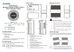
Power Supply Connection
】
The series of device provides 4-pin power
supply input terminal blocks and supports
two independent DC power supply
systems, PWR1 and PWR2, which
supports non-polarity and anti-reverse
connection function, that the device can work normally after
reverse connection.
Voltage range: 12~48VDC.
【
Relay Connection
】
Relay terminals are a set of normally open
contacts of the device alarm relay. They are
open circuit in the state of normal non alarm,
closed when any alarm information occurs. For
example, they are closed when powered off, and send out
alarm. The product supports 1 relay alarm information output
that can output DC power supply alarm information or network
abnormality alarm. It can be connected to alarm light or alarm
buzzer or other switching value collecting devices, which can
timely inform operators when the alarm occurs.
【
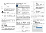
DIP Switch Settings
】
The series of devices provide 4-bits DIP switch for
function setting, where "ON" is enable valid terminal.
The definitions of DIP switch are as follows:
PIN Definition
Operation
1
Reboot
Set the switch to ON, then set it
to OFF after 1-2 seconds, the
system will reboot automatically.
2
Restore Factory
Settings
Set the switch to ON, then set it
to OFF after 5 seconds, the
system will automatically restore
the factory settings.
3-4
Reserved
—
【
Console Port Connection
】
The series of device provides 1 program debugging port
based on RS232 serial port which can conduct device CLI
command management after connecting to PC. The interface
adopts RJ45 port, the RJ45 pin definition as follows:
Pin No.
2
3
5
Definition
TXD
RXD
GND
【
Checking LED Indicator
】
The series of devices provide LED indicators to monitor its
operating status, which has simplified the overall
troubleshooting process. The function of each LED is
described in the table below:
LED
Indicate Description
P1
ON
Power P1 is connected and running
normally
OFF
Power P1 is disconnected or
running abnormally
P2
ON
Power P2 is connected and running
normally
OFF
Power P2 is disconnected or
running abnormally
ALM
ON
Power supply or port link has alarm
OFF
Power supply and port link have no
alarm
RUN
ON
The device is powering on or the
device is abnormal.
OFF
The device is powered off or the
device is abnormal.
Blinking
Blinking 1 time per second, the
device is running normally.
Link/Act
(1-16/20)
ON
Ethernet port has established a
valid network connection
Blinking
Ethernet port is in an active
network status
OFF
Ethernet port has not established
valid network connection
【
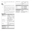
Logging in to WEB Interface
】
This device supports WEB management and configuration.
Computer can access the device via Ethernet interface. The
way of logging in to device’s configuration interface via IE
browser is shown as below:
Configure the IP addresses of computer and the
Step 1
device to the same network segment, and the
network between them can be mutually accessed
Enter device’s IP address in the address bar of the
Step 2
computer browser.
Enter device’s username and password in the login
Step 3
window as shown below.