3onedata IES5024-P Скачать руководство пользователя страница 3

5.


The power LED 

6.


Relay alarm LED 

7.


Rackmount ears 

8.


Power input and Relay output terminal block 

9.


10/100BaseT(X) (RJ45) ports 

10.


100Base-FX ports 

11.


Rear panel connector LEDs 

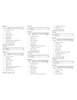
IES5024-20F-P (100~240VAC/DC) 

Front panel 


Rear panel 


1.


Restore factory settings 

2.


Console port 

3.


Link/ACT LEDs 

4.


Systems running LED 

5.


Relay alarm LED 

6.


The power LED 

7.


Power input and Relay output terminal block 

8.


10/100BaseT(X) (RJ45) ports   

9.


100Base-FX ports 

10.


Rear panel connector LEDs 

IES5024-24F-P (100~240VAC/DC) 

Front panel 


Rear panel 


1.


Restore factory settings 

2.


Console port 

3.


Link/ACT LEDs 

4.


Systems running LED 

5.


Relay alarm LED 

6.


The power LED 

7.


Power input and Relay output terminal block 

8.


100Base-FX ports 

9.


Rear panel connector LEDs 

Power supply input


The  Industrial  Ethernet  switches have  singe power and 

redundancy power  two kinds of power input.  The singe power 

series rear panel provides 5 bit wiring terminal for 

100~240VAC/DC  power entered (L/+, GND, N/-) and relay 

output (R+, R-).The unmanaged Ethernet switch relay alarm 

function is invalid. Terminal diagram is as follows: 


The redundancy power series rear panel provides two 

terminal blocks (5 bits) for P1 and P2 input. The redundant power 

can be used independently. P1 and P2 can  supply power at the 

same time, once either of these two powers fails, another power 

can acts as backup automatically to ensure reliability of the 

network.  Voltage input range is 100

240VAC/DC  (terminal 

block defined as P1: L/+, GND, N/-; P2: L/+, GND, N/- ). 

Important notice: 

1.


Power ON operation: first of all, insert power cable’s terminal 

block into device’s power port, then insert power supply plug into 

power source 

2. Power OFF operation: First off all, unpin power plug, then 

strike the terminal block, please take care of operation sequence.


Dimension


The series of products are the same size, and the number of the 

Ethernet interface is different. Unit (mm) 

Single Power Series 


Redundancy Power Series


Содержание IES5024-P

Страница 1: ... designed with low consumption and without fan The rugged hardware design makes the IES5024 perfect for ensuring that your Ethernet equipment can withstand the rigors of industrial applications Packing list Please check the packaging and accessories by your first using Industrial Ethernet switch ⅹ 1 User manual ⅹ 1 Documentation and software CD ⅹ 1 Certificate of quality ⅹ 1 Warranty card ⅹ 1 Plea...

Страница 2: ...6 Relay alarm LED 7 Rackmount ears 8 Power input and Relay output terminal block 9 10 100BaseT X RJ45 ports 10 100Base FX ports 11 Rear panel connector LEDs IES5024 8F P 100 240VAC DC Front panel Rear panel 1 Restore factory settings 2 Console port 3 Link ACT LEDs 4 Systems running LED 5 The power LED 6 Relay alarm LED 7 Rackmount ears 8 Power input and Relay output terminal block 9 10 100BaseT X ...

Страница 3: ...e power series rear panel provides 5 bit wiring terminal for 100 240VAC DC power entered L GND N and relay output R R The unmanaged Ethernet switch relay alarm function is invalid Terminal diagram is as follows The redundancy power series rear panel provides two terminal blocks 5 bits for P1 and P2 input The redundant power can be used independently P1 and P2 can supply power at the same time once...

Страница 4: ... X port of Converter and HUB 10Base T 100Base TX are used in MDI MDI X the define of Pin in the table as below NO MDI signal MDI X signal 1 TX RX 2 TX RX 3 RX TX 6 RX TX 4 5 7 8 Note TX Transmit Data RX Receive Data Not Use MDI straight through cable MDI X Cross over cable MDI MDI X auto connection makes switch easy to use for customers without considering the type of network cable 100Base FX Fibe...

Страница 5: ...not be overlapped and mixed when they are in the same groove road When cable is too long it cannot hold down other cable but structure in the middle of alignment rack 8 Pigtail cannot be tied and swerved as less as possible Swerving radius cannot be too small small swerving causes terrible loss of link Its banding should be moderate not too tight and should be separated from other cables 9 It shou...

Страница 6: ...ption 19 4W Full load consumption 20 4W IES5024 24F P 100 240VAC DC Unload consumption 22 0W Full load consumption 23 0W Working environment Working temperature 40 75 Storage temperature 40 85 Relative Humidity 5 95 no condensation Mechanical Structure Shell IP30 protect grade metal shell Installation 19 1U rack Size W H D 441 6mm 45mm 208 9mm Industry Standard EMI FCC Part 15 CISPR EN55022 class ...

Отзывы: