


supply specification to avoid over-voltage damaging the
device.
The device surface temperature is high after running;
please don't directly contact to avoid scalding.
【
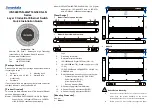
Rack-mounted
】
This product adopts 1U rack-mounting, mounting steps as
below:
Select the device mounting location to ensure
enough size.
Adopt 4 bolts to install the mounting lugs in the
device position as figure below.
Place the device in the rack; adopt 4 bolts to fix two
sides mounting lugs in the rack.
Check and confirm the product is mounted firmly on
the rack, mounting ends.
【
Disassembling Device
】
Power off the device.
Adopt screw driver to loosen the 4 bolts fixed on
the mounting lugs in the rack.
Shift out the device from rack, disassembling ends.
Notice before power on:
Power ON operation: First insert the power supply
terminal block into the device power supply interface,
then plug the power supply plug contact and power on.
Power switch “—” means power ON, “O” means power
OFF.
Power OFF operation: First, put the powers switch to
the "O" side and then disconnect the power supply.
Finally disconnect the connector between the device and
the power cord. Please notice the operation order above.
Please be aware of the power input range supported by
the device before powering on. Use the recommended
voltage of the device to avoid device damage.
【
Power Supply Connection
】
DC power supply (Model I)
Model I provides 5-pin 5.08mm pitch
terminal blocks and the built-in dual
power supply redundancy supports
DC power input. The power input
supports 1 single power supply input
or 2 power supply inputs at the same time; When two power
supply input at the same time, it supports redundant backup of
power supply. If one power supply fails, the device can still
work normally without interruption. Power supply supports
anti-reverse connection, which cannot power the device but
won’t damage it when it's reversely connected. The definitions
of power pin are shown in the left figure, and the power input
range is 24VDC/48VDC (12~55VDC).
AC power supply (Model II)
Model II provides 2 AC power sockets
with switch, PWR1 and PWR2, and
supports AC power supply input. The
power input supports 1 single power
supply input or 2 power supply inputs
at the same time; When two power supply input at the same
time, it supports redundant backup of power supply. If one
power supply fails, the device can still work normally without
interruption. Power supply input range: 110VAC/220VAC
(85~264VAC).
【
Relay Connection
】
Provide 3-pin 5.08mm pitch terminal block,
support 1 relay alarm output. In power off
situation, R- and R+ are a group of normally
closed contacts. After powered on, the relay is
open circuit in normal non-alarm state by default, closed when
any alarm information occurs. The relay supports power
supply alarm or network abnormality alarm. It can be
connected to alarm light or alarm buzzer or other switching
value collecting devices, which can timely inform operators
when the alarm occurs.
【
Console Port Connection
】
Provide 1 program debugging port based on
RS-232 serial port which can conduct device CLI
command management after connecting to PC.
The interface adopts RJ45 port, the RJ45 pin definitions are
as follows:
Pin No.
2
3
5
Definition
TXD
RXD
GND
【
Checking LED Indicator
】
The device provides LED indicators to monitor its operating
status, which has simplified the overall troubleshooting
process. The function of each LED is described in the table
below:
LED
Indicate Description
P1/P2
ON
Power P1/2 is running normally
OFF
Power P1/2 is disconnected or
running abnormally
ALM
ON
Power supply or port link has alarm
OFF
Power supply, port link without alarm
RUN
ON
The device is running abnormally
Blinking
Blinking 1 time per second, system
is running normally
OFF
The device is powered off or the
device is abnormal.
LINK
(G1-G40,
ON
Ethernet port has established a valid
network connection


