


Vehicle Equipment Installation Instructions
14
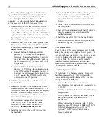
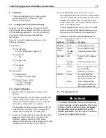
5.3 Radio/GPS Unit Cable Terminations
1. Route the cables from the radio/GPS antenna
through the vehicle to the radio/GPS unit
location.
2. Coil up any excess cable.
Note: When coiling excess cable do not create
any sharp bends in the cable or the cable may
be damaged.
3. Connect the cable labeled GPS to the GPS
connector on the radio/GPS unit. Connect
the other cable to the Radio connector.
Tighten the connectors using a 5/16” wrench
(an 8 mm wrench may also be used)
Note: The connectors are keyed and cannot be
connected to the wrong connector.
4. Plug the 15 pin connector of the radio/GPS
cable (black cable) into the P1 connector of
the radio/GPS unit and tighten the screws.
3. Route the cable to the location where the
Vehicle Control unit will be installed.
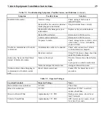
Table 5-1. Radio/GPS Unit Terminal Block
Pin Index
Pin
Wire Color
Function
1
Yellow
Radio transmit (+)
2
Yellow Black
Radio transmit (–)
3
Blue
Radio receive (+)
4
Blue White
Radio receive (–)
5
Orange
Radio clock (+)
6
Orange Green
Radio clock (–)
7
Brown
GPS power
8
Brown White
Common
9
Violet
Radio power
10
Violet White
Common
11
Bare
Shield drain wire
Figure 5-3. Radio/GPS Cable Installation
1. Vehicle radio/GPS unit
3. GPS antenna cable
2. Vehicle interface harness assembly
4. Radio antenna cable
Содержание Opticom
Страница 1: ...Installation Instructions February 2005 Opticom GPS Priority Control System Vehicle Equipment ...
Страница 26: ......
Страница 27: ...This page intentionally left blank ...
Страница 29: ...Vehicle Equipment Installation Instructions 25 Website www 3M com tss 1 800 3MHELPS 75 0301 0693 6 Rev C ...


