background image

Downloaded from Projector.com

RGB 1

10

 3M 1996

3M

 Multimedia Projector MP8030

Section 4: Operating the Projector

4-1. Turning On the Projector

Read the Important Safeguards before operating the 3M

Multimedia Projector MP8030.

Refer to Section 3 to make all cable connections. When the input cables and power cords are connected, turn
on the power, adjust the size and focus of the projected image and begin your presentation.

Power On: Turn on the projector power, then turn on the power to your input sources. The projector power
switch is located in the lower right corner of the input terminal panel.

Press the power switch to ON to apply power to the projector.

|

 = ON

   O

 = OFF

Caution

!

Allow a projector that has been stored in a cold
place to warm up to operating temperature 0

°

C

to 35

°

C (32

°

F to 95

°

F) before applying power.

The ON indicator on the projector control panel will turn orange, indicating the unit is in the standby mode.

Note

The lamp does not energize in the standby mode.

Remove Lens Cap: Remove the lens cap from the projection lens before energizing the lamp.

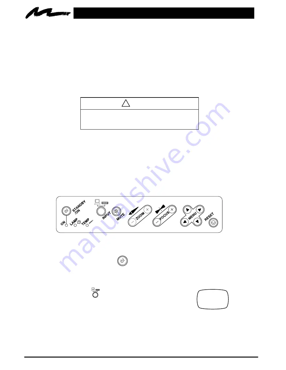
Projector Control Panel: The projector control panel (Figure 4-1) is located on the top of the projector. Use
these buttons to control the projector functions or use the remote control transmitter.

VIS–41L

Figure 4-1. Projector Control Panel

Energize Lamp: Press the STANDBY/ON  

 button to energize the lamp. The ON indicator will blink as

the metal halide lamp warms up. It takes a few moments for the lamp to reach its full light output. When the
lamp is ready, the ON indicator turns solid green.

Select Input: Press the INPUT

button to select the desired computer video       

source or video source.  Press the INPUT button again to select the next input 
source.  The input sources are selected in the following sequence: 

RGB1 

RGB2 

Video1 

 Video2 

RGB1 ... etc.

The following Error Messages may display if there is a video input problem:

NO INPUT DETECTED

Cables are not connected to
input jacks or input source is
off.

SYNC IS OUT OF RANGE

The connected input source
is not compatible with the
MP8030.

Содержание Multimedia Projector MP8030

Страница 1: ...e do not make any claim of copyright The copyright remains the property of their respective owners ABOUT PROJECTOR COM Projector com http www projector com is your review and buying guide resource for DLP and LCD video projectors Visit the site to read the latest projector news and reviews read and comment on projector specifications download user manuals and much more ...

Страница 2: ...e MP8030 Appareil de projection multimédia Guide de l opérateur MP8030 Multimedia Projektor Bedienerhandbuch Portatil Multimedia MP8030 Manual del usuario MP8030 Projettore multimedia Manuale dell operatore MP8030 Multimedia Projektor Instruktionsbok MP8030 Multimedia Projector Gebruiksaanwyzing ...

Страница 3: ...f the Projector 11 4 3 Memory Function Factory Defaults 11 4 4 Adjusting the Picture 12 4 5 Using System Menus 12 4 6 Setup Menu RGB and Video Picture 13 4 7 Input Menu 14 4 7 1 Selecting the Input Source 14 4 8 Image Menu 14 4 8 1 Inverting the Image 14 4 8 2 Changing the Screen Background Color Blank Button 14 4 8 3 Changing the Screen Reveal Rate 15 4 8 4 Changing the Menu Size 15 4 8 5 Display...

Страница 4: ...ning 21 Section 8 Troubleshooting 23 8 1 Service Information 23 Section 9 Technical Specifications 24 9 1 Specifications 24 9 2 Projector to Screen Distances 24 9 3 Physical Dimensions 25 9 4 Computer Video RGB Input Signal 25 9 5 Computer Video RGB Input Terminal 26 9 6 S Video Input Signal Terminal 26 9 7 RS 232 Cable Mouse Control 26 Section 10 Accessories 27 10 1 Multimedia Projector Accessori...

Страница 5: ...e warranty shall be void if the customer fails to operate product in accordance with 3M s written instructions This warranty gives you specific legal rights and you may have other rights which vary from state to state FCC STATEMENT CLASS A This equipment generates uses and can radiate radio frequency energy and if not installed and used in accordance with the instruction manual may cause interfere...

Страница 6: ...th a current rating at least equal to that of the appliance should be used Cords rated for less amperage than the appliance may overheat 8 Always unplug appliance from electrical outlet before cleaning and servicing and when not in use Grasp plug and pull to disconnect 9 Let appliance cool completely before putting away or when replacing lamp Loop cord loosely around appliance when storing 10 Disc...

Страница 7: ...cluded Video Cable S Video mini DIN4 pin Lens Cap 3 Power Cords VGA Cable 15 15 pin M M Apple MAC II Video Adaptor Cable 15 15 pin F M 3 Conductor Video AudioCable U S U K Europe RS 232 Cable 9 pin M M Stereo Mini Jack Cable Figure 1 1 Inventory of Shipping Box 1 2 Keep Your Packing Materials Save the shipping box and packing materials in the event the MP8030 should require shipping to a 3M Servic...

Страница 8: ... rear projection or ceiling mount D Horizontal and vertical image position control D On screen menu displays in your choice of seven different languages D On screen menu to adjust video image tint brightness color contrast sharpness video system screen blank color timer reveal rate and menu size D On screen menu to adjust computer video RGB synchronization image brightness sharpness horizontal pha...

Страница 9: ... the side of the projector Connect your first input source to the Terminal 1 connectors and your second input source to the Terminal 2 connectors Terminal connectors for VIDEO AUDIO 1 2 are S Video Video Audio L and Audio R Terminal connectors for Computer1 RGB1 are RGB In and Audio In 1 Terminal connectors for Computer2 RGB2 are RGB In Audio In 2 and Control Terminal connectors for output are RGB...

Страница 10: ...le and adapts it to fit Apple MAC II computers and Apple MAC Powerbook laptop computers Connect the CRT cable into the RGB Out terminal to view the image on both the monitor and MP8030 Figure 3 4 IBM PC Computer Figure 3 5 Apple MAC II Computer S Video Connection Some video devices can generate S VHS video or S Video Y C The MP8030 will accept this signal through the S VIDEO1 or S VIDEO2 connector...

Страница 11: ...pointing device is disabled reboot the PC and the operating system DOS Windows should recognize the MP8030 stick switch as the pointing device 3 2 Projector SetUp The meeting room is your operating environment and any stray light hitting the projection screen will become glare It is best to use a meeting room without wide open windows If there are light stripes from venetian blinds try to find a v...

Страница 12: ...endicular 90 to the lens Measured from the center of the projection lens the top to bottom projected image Figure 3 10 is projected with most of the image above the center of the lens and a small amount below the center of the lens The position of the projected image to the center of the lens is an important consideration for the vertical placement of the projection screen Use the table below to c...

Страница 13: ...on adjustments can be made by turning the foot in a clockwise or counterclockwise direction Ceiling Mount Considerations An optional ceiling mount bracket Figure 3 12 is required to install the MP8030 from the ceiling For this type of installation the image must be inverted Refer to Section NO TAG Inverting the Image for more details 90 Figure 3 12 Optional Ceiling Bracket Viewingfrom backside of ...

Страница 14: ...e standby mode Note The lamp does not energize in the standby mode Remove Lens Cap Remove the lens cap from the projection lens before energizing the lamp Projector Control Panel The projector control panel Figure 4 1 is located on the top of the projector Use these buttons to control the projector functions or use the remote control transmitter VIS 41L Figure 4 1 Projector Control Panel Energize ...

Страница 15: ...menu Press the up down MENU arrow or left right MENU arrow again to select highlight the desired menu option See Section 4 5 for more about using menus Volume Adjustment Use the VOLUME button on the remote control to adjust the speaker volume Press to increase or to decrease the volume level See Section 4 6 to set the volume in the Setup menu 4 2 Turning Off the Projector Press and hold down the S...

Страница 16: ... 4 1 or the remote control transmitter Figure 5 1 to access menus exit menus and set menu options Press MENU on the projector panel or MENU on the remote control to display the names of the system menus across the top of the projection screen Figure 4 2 To select one of these menus press the left right menu arrow MENU on the projector control panel or move the remote control stick switch left righ...

Страница 17: ...n to the video or RGB image 4 6 Setup Menu RGB and Video Picture Press the left right menu arrow MENU or move the stick switch left right to select the SETUP menu Depending on the current input source either the RGB menu or Video menu will display SETUP INPUT IMAGE OPT VOLUME BRIGHT CONTRAST V POSIT H POSIT H PHASE H SIZE 99 101 14 800 SETUP INPUT IMAGE OPT VOLUME BRIGHT CONTRAST SHARPNESS COLOR T...

Страница 18: ...lay VIDEO1 SETUP INPUT IMAGE OPT RGB1 RGB2 VIDEO2 TEST PATTERN SYSTEM AUTO NTSC PAL SECAM Selectthis option Toselect RGB1 Computer 1 RGB terminal RGB2 Computer 2 RGB terminal VIDEO1 Video1 terminal AUTO NTSC PAL SECAM VIDEO2 Video2 terminal AUTO NTSC PAL SECAM TEST PATTERN Display the test pattern start up screen 4 8 Image Menu 4 8 1 Inverting the Image The image can be inverted for ceiling mounte...

Страница 19: ...the left right menu arrow MENU or move the stick switch left right to select the IMAGE menu then select the REVEAL sub menu See Stick Switch and Blank button descriptions in Section 5 1 REVEAL BLANK MIRROR SETUP INPUT IMAGE OPT MENU SIZE SLOW FAST REVEAL MEDIUM MESSAGE Select this option To adjust the following FAST Blank screen will reveal at a fast rate MEDIUM Blank screen will reveal at a mediu...

Страница 20: ...ter mouse control Press the left right menu arrow MENU or move the stick switch left right to select the SETUP menu and the COM SPEED sub menu The computer mouse for most IBM compatible computers will operate at a baud rate of 1200 COM SPEED SETUP INPUT IMAGE OPT COM BITS MOUSE TIMER LANGUAGE AUTO OFF MOUSE 2400 4800 9600 19200 COM SPEED bPS 1200 Select this option To adjust the following Communic...

Страница 21: ...Once the minutes for countdown timer are set press the TIMER button on the remote control to start stop the timer See remote control TIMER COM BITS COM SPEED SETUP INPUT IMAGE OPT MOUSE LANGUAGE AUTO OFF 20 TIMER min Select this option To adjust the following Timer Minutes up to 99 for the on screen countdown timer 4 9 5 Language Press the left right menu arrow MENU or move the stick switch left r...

Страница 22: ... period of time Press the left right menu arrow MENU or move the stick switch left right to select the OPT menu and the AUTO OFF sub menu To disable function set the wait period to 0 AUTO OFF COM BITS COM SPEED SETUP INPUT IMAGE OPT MOUSE TIMER LANGUAGE AUTO OFF 0 min STOP Select this option To adjust the following Automatic Off Wait period from 1 to 99 minutes before projector will switch to stan...

Страница 23: ...eft or right as needed to select a menu Press the menu button again to remove the menu and return to the video image Zoom Sizes the picture to fit the screen Press to make the projected image wider or to reduce the image size Focus Press or to focus the image Timer Press the timer button to display the timer and start the countdown Press the timer button again to stop the timer reset it to the ful...

Страница 24: ...vice or your dealer 6 2 Replacing the Lamp To replace the lamp the following is needed D Phillips screwdriver D Standard 2 screwdriver D Metal halide lamp Important Always use lamp type 260W Metal Halide 70 VDC 4 3A Part Number 78 6969 8262 4 Power OFF Press the Standby ON button on the projector control panel or remote control and wait for the fan motor to cycle off Then turn off the power switch...

Страница 25: ...rt the new lamp module into the opening and slide it all the way back into place Figure 6 5 Check the lamp module to be sure that it is fully inserted and flush against the back wall Tighten the lamp module retaining screws to secure the lamp module in place Figure 6 2 Insert the hinge tabs on the left side of the lamp access door then close and tighten the retaining screw to secure the door Figur...

Страница 26: ...an the air filter every 10 hours of operations Unplug the power cord and stand the projector upright with the bottom facing you Unscrew two retaining screws and pull down and out on the handle to free the air cleaner door Figure 7 2 Carefully pry out tabs and lift up on the retaining frame to free the air cleaner Figure 7 3 Air Cleaner Door Figure 7 2 Pull Down and Out to Remove Door Retaining Fra...

Страница 27: ...frame to the door Tab Slot Figure 7 5 Insert Frame and Air Cleaner Insert the hinge tabs on the door into the slots in the projector body and swing the door down Push on the handle to fully engage the door latch and then tighten the retaining screws to secure the door Figure 7 6 Note The air cleaner door must be closed and latched or power to the lamp will be shut off and the LAMP indicator will c...

Страница 28: ... and contrast Press MENU and select SETUP D Lamp may need replacement Call customer service for assistance See Service Information below Picture is not sharp and clear D Press FOCUS or buttons Adjust the sharpness video only Press MENU and select SETUP LAMP indicator is solid red D Turn the power off and let the projector cool After 20 minutes turn the power on If the LAMP indicator comes on again...

Страница 29: ...n Chroma 0 286V peak to peak burst signal 75Ω term Video 1 0V peak to peak 75Ω termination Audio 200mvRMS across 20kΩ Output signals Audio 200mvRMS across 20kΩ Batteries for remote control Two AA 1 5 Volt 9 2 Projector to Screen Distances Distance to Screen 223 cm 7 3 ft 341 cm 11 2 ft 436 cm 14 9 ft 570 cm 18 7 ft 686 cm 22 5 ft 860 cm 28 2 ft 1173 cm 38 5 ft Screen Diagonal Min Zoom 102 cm 40 in...

Страница 30: ...solution H X V fH kHz fV Hz Sync Signal Interlaced Note 15 kHz RGB NTSC 15 7 60 H V composite yes VGA 1 IBM compatible 640 x 350 31 5 70 H V separate H Positive V Negative no VGA 2 IBM compatible 640 x 400 31 5 70 H V separate H Negative V Positive no VGA 3 IBM compatible 640 x 480 31 5 60 H V separate H Negative V Negative no Macintosh 13 in mode Apple 640 x 480 35 0 66 7 H V separate H V composi...

Страница 31: ... composite sync signal 6 Ground red 14 Vertical sync signal 7 Ground green 15 No Connection 8 Ground blue 9 6 S Video Input Signal Terminal The following illustration Figure 9 2 identifies the terminal connections for the Mini DIN4 pin Luminance Signal Chrominance Signal Ground Ground Figure 9 2 S Video Input Mini DIN4 pin Video input signal terminals are detected by the MP8030 in the following or...

Страница 32: ...fe Cedex France 3M Canada P O Box 5757 London Ontario N6A 4T1 Let us help you make the most of your next presentation We offer everything from presentation supplies to tips for better meetings And we re the only transparency manufacturer that offers a recycling program for your used transparencies For late breaking news handy references and free product samples call us toll free in the continental...

Страница 33: ...e do not make any claim of copyright The copyright remains the property of their respective owners ABOUT PROJECTOR COM Projector com http www projector com is your review and buying guide resource for DLP and LCD video projectors Visit the site to read the latest projector news and reviews read and comment on projector specifications download user manuals and much more ...

Отзывы: