27
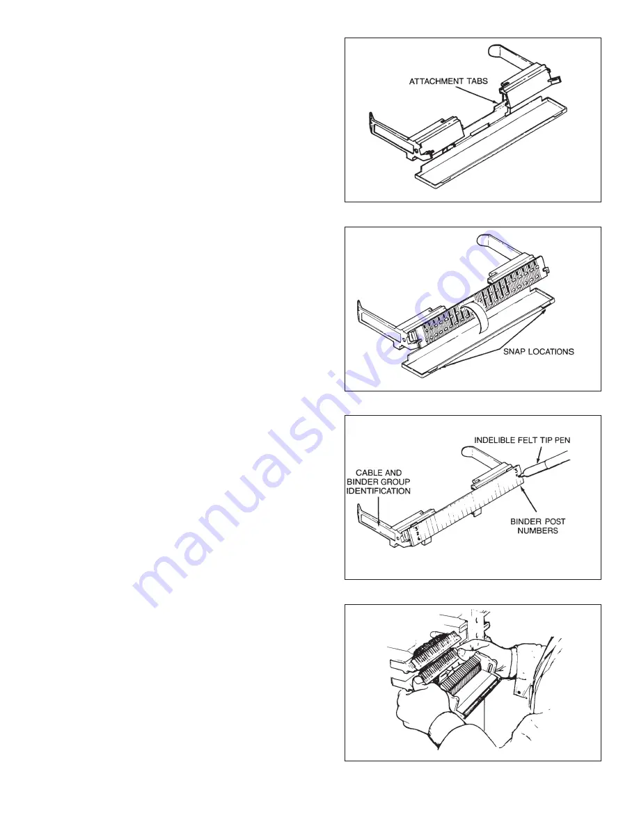
2. Insert Attachment Tabs to module mount on
underside. See Figure 67.
3. Mount module and snap Module Protector over
face of module. See Figure 68.
4. Identify pairs by marking on the matte-finished
cover with an indelible marking pen. See
Figure 69.
b. Continue the termination of the modules. See
Figure 70.
IMPORTANT: For 4065 300-Pair Cabinet: Install a
mount set and the adjustable wire run guide to separate
the feeder and distribution modules.
When next to last Module has been terminated, remove
head. Lift Module off head and snap into place. Put Splicing
Head Frame Adapter back into the same (last) frame holes
and splice last Module. Remove Head and Module and
snap Module into place. (Push any excess wire slack up and
behind Module.)
c. Mark ends of Modules with binder post or pair count
numbers. Install Module protectors.
Figure 67.
Figure 68.
Figure 69.
Figure 70.
Содержание MS2 4000 Series
Страница 2: ......
Страница 5: ... ...
Страница 21: ...21 Figure 46 Figure 47 ...
Страница 36: ...36 D Supply Information ...
Страница 37: ...37 ...
Страница 39: ...39 ...


