background image

Model C1060 Headset Intercom System 

Replacement Parts and Service 

©

3M  2005 November 


13 


Service Procedures 

(continued) 


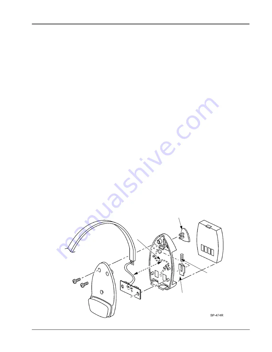
Replacing Battery Holder Parts 


Tools Required: 
 

1 – Number 0 Phillips Screwdriver 

1 – Soldering iron. 

 
Procedures: 
 
1. 

Make sure power is off and remove Battery.


2. 

Remove two screws and Cover.  (If replacing 
old style Battery Contacts, discard all Battery 
Holder parts, they are not compatible with 
newer Battery Holder parts.)


3. 

Unsolder the two Battery Holder PWA wires.


4. 

Insert the Headband wires through the holes 
from the back side of the replacement Battery 

Holder PWA.  Solder the 

RED

 wire to the 

+


connection point and the 

BLACK

 wire to the 

 connection point. 


5. 

Press the Battery Latch Spring onto the top 
peg of the Battery Latch.  Insert the Latch with 
Spring down through the top of the Base as 
shown.  The beveled bottom edge of the Latch 
MUST face the battery. 

6. 

Press the top of the Spring into the small 
molded ribs located inside the top of the Base. 

7. 

Insert the Battery Latch Button through the 
front of BOTH the Base and Latch.  Squeeze 
the parts until they snap securely together.


8. 

Press the Battery Holder PWA onto the pegs 
of the Base noting that one hole is larger than 
the other.


9. 

Place the hole in the Headband over the 
retaining peg in the Cover.  Route the power 
wires between the two posts near the top and 
the three posts near the bottom as shown.  Be 
careful to avoid pinching wires while 
replacing Cover and two screws.


10. 

Install new Headband Pad on Battery Holder 
Cover.


Battery Latch 
Button 

Battery Latch 

Battery Latch 
Spring 

Battery Holder PWA 

Power Wire 
Routing 

Содержание HEADSET C1060

Страница 1: ...er part number part name and quantity required Replacement parts and their prices are available by calling 1 800 328 0033 Replacement parts correspondence write to 3M Commercial Care Division Food Ser...

Страница 2: ...Model C1060 Headset Intercom System Replacement Parts and Service 3M 2005 November 2 Replacement Parts List continued Section 1 Base Station Assembly Interconnect Module and Programming Station...

Страница 3: ...9 BASE STATION ASSEMBLY Model C922 w o Power Supply 1 1 78 8095 0500 7 CABINET Base Station 1 1A 78 8095 0965 2 HINGE Assembly Replacement 1 2 78 6911 4430 3 POWER SUPPLY 13 5 VDC 20 VA 1 3 78 6911 37...

Страница 4: ...C1060 Headset Intercom System Replacement Parts and Service 3M 2005 November 4 Replacement Parts List continued Section 2 Headset Assembly 1 2 3 4 5 6 7 8 9 10 11 12 13 14A 14B 14C 14D 15 16 18 17 20...

Страница 5: ...ver Battery Holder 1 11 N A separately Button Battery Latch 1 12 N A separately Latch Battery 1 13 N A separately Spring Battery Latch 1 14 N A Mic Boom 1 14A N A Washer Nylon Mic Boom 1 14B N A Washe...

Страница 6: ...d Service 3M 2005 November 6 Replacement Parts List continued Section 3 3 Slot Battery Charger Assembly Item No Part Number Description Qty 1 78 6911 4724 9 BATTERY CHARGER 3 Slot for Model C1060 1 2...

Страница 7: ...acement Parts and Service 3M 2005 November 7 Section 4 6 Slot Battery Charger Assembly Item No Part Number Description Qty 1 78 6911 4725 6 BATTERY CHARGER 6 Slot for Model C1060 1 2 78 8028 9283 2 PO...

Страница 8: ...up and Ear Pad together free of the speaker on the Inner Case 2 Separate the Ear Pad from the Ear Cup Replace Ear Pad and or Ear Cup with a new one and reassemble 3 Twist and press into place over spe...

Страница 9: ...s by pulling the Inner Case down then apart at the bottom Carefully raise the Inner Case just over the On Off Button and slide down slightly to separate Support the Inner Case so the speaker cable is...

Страница 10: ...ng ring tool adjustment screw to limit how far the retaining ring is expanded Unless this is done the retaining ring will stretch out of shape to a point where it will not stay in its groove 2 Remove...

Страница 11: ...groove up and side slot facing Headband Insert on Headband and rotate 90 degrees in place 7 Carefully press the power wires one on top of the other into the open wire groove of the Headband Clip Be su...

Страница 12: ...power cable and Headband through the top of Outer Case with Headband curve arching away from the front of the Outer Case 11 Grasp Headband Clip with open wire groove up and side slot facing Headband...

Страница 13: ...ing onto the top peg of the Battery Latch Insert the Latch with Spring down through the top of the Base as shown The beveled bottom edge of the Latch MUST face the battery 6 Press the top of the Sprin...

Страница 14: ...ore replacing the case screws It is a good idea to simply snap the case together without the screws until the headset is completely checked out 1 Make sure a fully charged battery is installed in the...

Отзывы: