


22
087-0020 REV
E
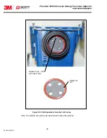
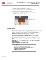
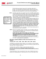
Figure 4 Inside View
Power Supply
& I/O PCB
P/N 096-2499
CPU board is
located behind
power supply PCB
P/N 096-2498 (SST)
P/N 096-2498-1 (no
SST option)
Display PCB
P/N 096-2497
Cable assembly
P/N 096-2613
See Figure 22 in rear
of manual for sensor
connector wiring
legend and applicable
customer non-
hazardous area wiring
connections to
terminal block.
Intrinsically Safe wiring
diagram shown in
Figure 21 at rear of
manual
Freedom 5000 Universal Analog Toxic Gas Detector
Instruction Manual


