


3
Status Indication
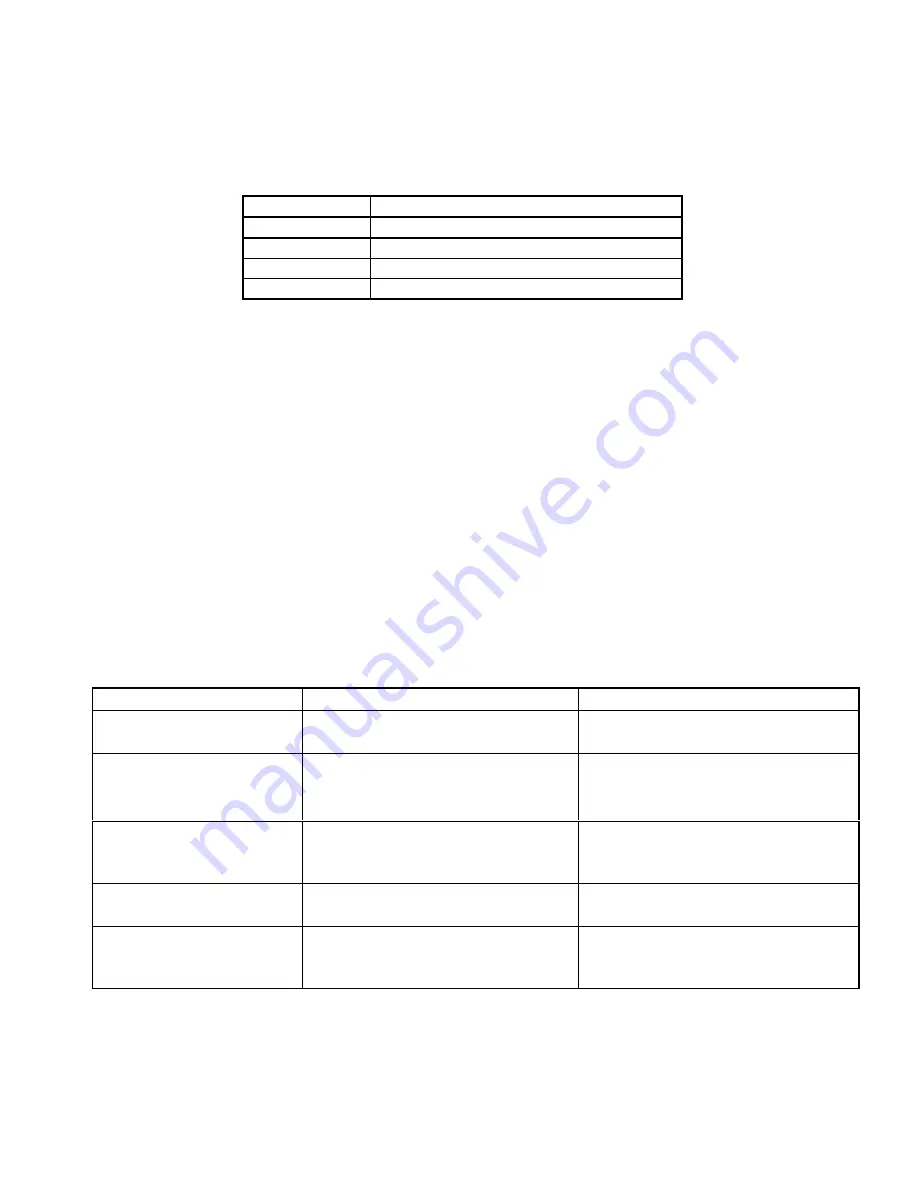
The condition of the red LED on the 3M C960 base station indicates the current status of the unit. The LED can
be off, blink at defined intervals, or be constantly lit. Table 3 illustrates the status indicated by the LEDs.
Status
LED
Power OFF
LED Off
Normal Mode
LED blinks once per every two seconds
Test Mode
LED blinks three times per second
Fault Condition
LED is solid red (constantly lit)
Table 3. A125 Status Indication
Final Checkout Procedure
1.
On the C921BA Base Station, turn the NRM ON/OFF switch ON. The red LED should blink slowly. Listen
for a reduction in the background noise.
2.
If the A125 is in a half-duplex system, set SW2 number 2 OFF and proceed to step 3.
If the A125 is in a full-duplex system set SW2 number 2 OFF. Speak into the headset microphone. The
echo should increase. Turn SW2 number 2 back ON. The echo should decrease.
3.
Set SW2 number 3 for appropriate level of noise reduction. Set SW2 number 3 OFF for restaurant mode.
Set SW2 number 3 ON for truck stop mode.
4.
Set SW2 number 4 (Hi Frequency Equalization) to customer’s preference.
5.
Check the inbound audio level of headset if TALK LOCK feature is used. Attempt to adjust the inbound
level when background noise in restaurant is at a high level.
Troubleshooting
Problem
Possible Cause
Correction
1. Status fault indicated.
Inbound audio exceeded maximum
level.
Switch A125 OFF for one second.
2. No inbound audio.
Mode setting is incorrect.
Check mode configuration.
Check wiring from post to base station.
Reinstall A125 module.
3. Loud audio in 3M
headset when headset user
talks.
Inbound audio on 3M base station too
low.
Increase MENU MIC SENS
potentiometer. Headset user should
then reduce the headset audio volume.
4. Excessive echo
Excessive feedback from menu
speaker to menu mic.
Add extra acoustic insulation to menu
mic chamber.
5. Low inbound audio when
using C960/C860 TALK
LOCK feature.
Background noise inside restaurant
may cause inbound audio to be
reduced.
Increase MENU MIC SENS
potentiometer.
Table 4. A125 Noise Reduction Module Troubleshooting
Содержание C960
Страница 3: ...Model C960 Headset Intercom System Revision History b E 3M 2000 May Blank Page ...
Страница 7: ...Model C960 Headset Intercom System Table of Contents iv E 3M 2000 May Blank Page ...
Страница 17: ...Model C960 Headset Intercom System Operation and Diagrams 1 10 E 3M 2000 May Blank Page ...
Страница 19: ...Model C960 Headset Intercom System Operation and Diagrams 1 12 E 3M 2000 May Blank Page ...
Страница 20: ...Model C960 Headset Intercom System Operation and Diagrams 1 13 E 3M 2000 May Interconnect Module Diagram ...
Страница 21: ...Model C960 Headset Intercom System Operation and Diagrams 1 14 E 3M 2000 May Blank Page ...
Страница 22: ...Headset Intercom Systems Model C960 C860 Installation Instructions ...
Страница 23: ......
Страница 32: ...7 Brown Yellow Figure 7 Connecting Components to the Interconnect Module ...
Страница 53: ...Model C960 Headset Intercom System Replacement Parts and Service 3 4 E 3M 2000 May Section 2 Headset Assembly ...
Страница 62: ...Model C960 Headset Intercom System Replacement Parts and Service 3 13 E 3M 2000 May Figure 3 7 ...
Страница 63: ...Model C960 Headset Intercom System Replacement Parts and Service 3 14 E 3M 2000 May Blank Page ...
Страница 70: ...Headset Intercom System Model C960 Operating Instructions ...
Страница 71: ......
Страница 75: ...Important Information Model C960 3M 1999 May iv Blank Page ...
Страница 109: ...4 Figure 2 Wiring for 3M C760 C960 Base Station with Interconnect Module ...
Страница 140: ...2 5 Connect the cables from the module to the base stations as shown in Figure 1 Figure 1 ...
Страница 153: ...3 Figure 2 Attenuator Connections ...
Страница 156: ...2 Figure 1 Typical Installation on a Speaker Post ...
Страница 157: ...3 Figure 2 Speaker Mounting Template ...